Method of nondestructive testing with digital shearing speckle interferometry and device thereof

A speckle interference and non-destructive testing technology, which is applied in the direction of optical testing flaws/defects, etc., can solve the problem that the sensitivity and resolution of digital shearing speckle interference technology cannot be further improved, and cannot achieve large field of view and high sensitivity at the same time. Focus and other problems, to achieve the effect of increasing the area, improving the sensitivity, and improving the sampling accuracy

Inactive Publication Date: 2010-04-28
NORTHWESTERN POLYTECHNICAL UNIV
View PDF2 Cites 16 Cited by
  • Summary
  • Abstract
  • Description
  • Claims
  • Application Information

AI Technical Summary

Problems solved by technology

Therefore, non-destructive testing based on area array CCD cannot meet the requirements of large field of view and high sensitivity at the same time.
In addition, if the surface of the material to be tested has large fluctuations, exceeding the depth of field limit of the imagin

Method used


Image

  • Method of nondestructive testing with digital shearing speckle interferometry and device thereof
  • Method of nondestructive testing with digital shearing speckle interferometry and device thereof
  • Method of nondestructive testing with digital shearing speckle interferometry and device thereof

Examples


Example Embodiment

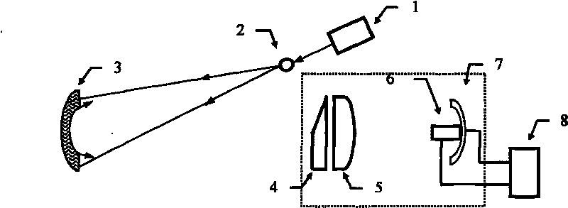
[0042] The working mode and process of embodiment 2 are basically the same as embodiment 1, and the difference is that in embodiment 2, the surface of sample 3 is distributed in different planes through cylindrical lens 3 due to the fact that the surface of sample 3 is a non-plane. Therefore, the trajectory of the micro-displacement platform 7 that can be moved in two-dimensional directions is a curve consistent with the fluctuation of the image plane, so that the speckle image in the final synthesized two-dimensional sheared speckle image is clearly in focus.

[0043] The beneficial effect of this embodiment is that when the surface of the sample to be tested has large fluctuations, such as the inner surface of a tire, the moving track of the micro-displacement platform can be designed according to the elliptical shape of the inner surface, so that each image point on the obtained shear speckle pattern Clear in focus; the introduction of the cylindrical lens makes no aberratio...


PUM


Abstract

The invention relates to a method of nondestructive testing with digital shearing speckle interferometry and a device thereof. The method is characterized of comprising the steps: directing an expanded laser beam onto the surface of a sample to be sheared; linear array CCD scanning to obtain two telescoped speckle images H1 which are formed by two scattered light beams and on the surface of the sample to be tested; vacuumizing the sample to be tested to obtain the other image H2; relatively operating the image H1 before the vacuumization and the image H2 after the vacuumization to obtain an image H3; and filtering the image H3 by means of average filtering or median filtering, wherein if interference fringe with the shape of butterfly rash s existed in a image H4, the sample is tested to be broken, otherwise, the sample is tested to be nondestructive. By using the linear array CCD scanning method, a corresponding moveable track of a micro-mobile platform can be designed according to the surface of the sample to be tested, and the speckle obtained by scanning along the moveable track removes the defocusing phenomenon of the speckle image, thereby effectively improving the sensitivity of the defect testing.

Description

technical field [0001] The invention relates to a method and device for non-destructive testing by using digital shear speckle interference, and belongs to the technical field of optical non-destructive testing. Background technique [0002] Digital shear speckle interferometry is a laser-based full-field, non-contact measurement of surface deformation (displacement or strain). A shearing mirror with a small wedge angle is placed in front of the imaging lens, so that a point on the surface of the object produces a pair of two images with a small misalignment on the image plane. Since the surface of the object is illuminated by the laser, the image caused by the misalignment The two clipped images interfere with each other to form a clipped speckle field containing a random interference pattern. Dislocation images interfere with each other on the image plane to form a speckle interference image, which is collected by the CCD into the computer through the image acquisition ca...

Claims


Application Information

Patent Timeline
IPC IPC(8): G01N21/88
Inventor 赵建林邸江磊孙伟伟王倩焦向阳
Owner NORTHWESTERN POLYTECHNICAL UNIV
Why Eureka
Try Eureka