
Electron gun assembly die and assembling method thereof

A technology for electron guns and molds, which is applied in the manufacture of electrical components, electrode assemblies, DC voltage accelerators, etc., can solve problems such as precision and tooling difficulty, and achieve the effects of improving yield, preventing current heating, and ensuring electron optical parameters.

Active Publication Date: 2010-04-28
CGN DASHENG ELECTRON ACCELERATOR TECH
View PDF0 Cites 4 Cited by
  • Summary
  • Abstract
  • Description
  • Claims
  • Application Information

AI Technical Summary

Problems solved by technology

[0004] The invention provides an assembly mold and assembly method for an electron gun, which solves the problems of accuracy and difficulty of the tooling in the tooling of the electron gun

Method used


Image

  • Electron gun assembly die and assembling method thereof
  • Electron gun assembly die and assembling method thereof

Examples


Embodiment Construction

[0020] Below in conjunction with accompanying drawing description, the present invention is described in further detail:

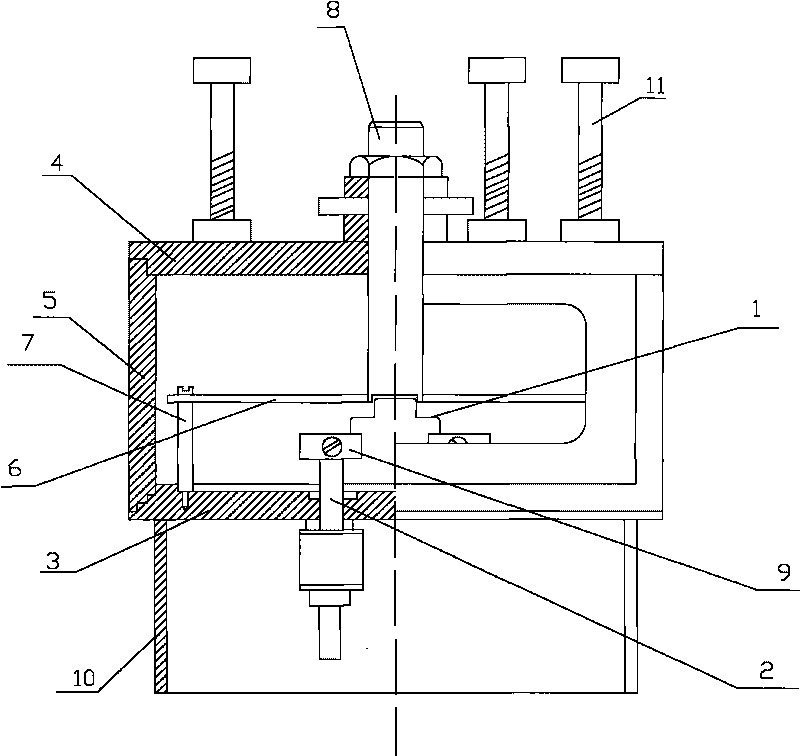
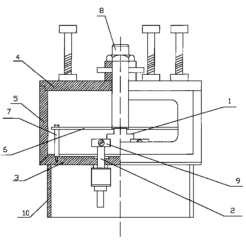
[0021] like figure 1 Shown: an assembly mold for an electron gun, including an upper positioning mold 4, a sleeve mold 5, and a support seat 10. The cover of the upper positioning mold 4 is pressed on the sleeve mold 5, and the support base 10 is placed under the gun cover plate, and the center positioning is also included. 8; the center positioning member 8 is arranged at the center of the upper positioning mold 4, and also includes an upper support 11; the upper support 11 is arranged on the upper positioning mold 4, and the upper support 11 is set thread.

[0022] A method for assembling the described electron gun assembly mold, comprising the following steps:

[0023] 1) After the lead electrode 2 and the gun cover 3 are welded and formed, the gun cover 3 is installed with one end of the non-inductive filament 1 facing upwards and placed on the suppo...


PUM


Abstract

The invention relates to an assembly die, in particular relates to an electron gun assembly die and an assembling method thereof. The electron gun assembly die comprises an upper location die, a cover die and a supporting seat, wherein the upper location die covers and presses on the cover die; and the supporting seat is placed under a cover plate of the gun. Through the whole set of assembly dies of the electron gun and a proper technical operation process, a non-inductive electron-tube heater and a lead electrode can be well contacted so as to avoid current fluctuation or more serious consequences caused by heat emission and ignition of current, ensure concentricity of an emitting surface of the non-inductive electron tube heater, a focusing electrode hole and a shoulder surface of the cover plate of the gun and non-deviated non-defocused electron bunch. The assembly die ensures the interelectrode distance between the emitting surface of the non-inductive electron tube heater and an end surface of a focusing electrode, contributes to electron emission. By the die and the correct technical operation, the yield of the electron gun can be improved, the optical parameter requirement of electrons can be ensured, and parts of the electron gun have good interconvertibility and other significant effects.

Description

technical field [0001] The invention relates to an assembly mold, in particular to an electron gun assembly mold and an assembly method. Background technique [0002] The electron gun is an important part of the electric vacuum device and the acceleration equipment. It is the source of the electron beam, and it also affects the "quality" of its work, and affects the working status and economic benefits of the equipment. It is heated by electric heating tungsten wire, so that it has a certain electron emission ability. Under the action of the electric field of the focusing electrode and the anode (also known as the suction electrode), it generates an electron beam current that meets the design requirements. Therefore, it is necessary to ensure a high-fidelity seal for the electrons. The electron gun cover plate is centered with the accelerator flange, and the required distance between electrodes is maintained to achieve good electrical parameters, etc., and the expected life ...

Claims


Application Information

Patent Timeline
Patent Type & Authority Applications(China)
IPC IPC(8): H01J9/18H05H5/02H05H7/00H05H7/22
Inventor 侯俊山俞江李健辉
Owner CGN DASHENG ELECTRON ACCELERATOR TECH
Learn More