Check patentability & draft patents in minutes with Patsnap Eureka AI!

Laser backlight surface light source

A technology of laser light source and backlight surface, applied in the field of laser display, can solve the problems of small color gamut, difficulty in starting at low temperature, non-compliance with environmental protection standards, etc., and achieve the effect of improving spatial resolution and improving energy utilization rate

Inactive Publication Date: 2010-05-05
SHANDONG UNIV
View PDF0 Cites 11 Cited by
  • Summary
  • Abstract
  • Description
  • Claims
  • Application Information

AI Technical Summary

Problems solved by technology

[0003] 1. Cold cathode fluorescent tubes contain a small amount of mercury, which does not meet environmental protection standards;
[0004] 2. Light leakage is more common, it is difficult to start at low temperature, and the response time is longer;
[0005] 3. The color gamut range is smaller than that of CRT, and generally only reaches 72% of the NTSC color gamut standard, and the colors presented are not rich enough
However, LED backlight also has its disadvantages. Firstly, its brightness is not high enough, multiple LEDs are needed, power consumption is relatively large, and the range of color rendering is not large enough (compared with lasers).

Method used


Image

  • Laser backlight surface light source
  • Laser backlight surface light source
  • Laser backlight surface light source

Examples


Embodiment Construction

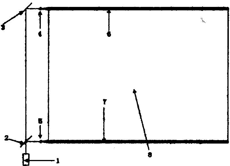
[0020] Such as figure 1 As shown, the laser backlight surface light source of the present invention includes a laser light source 1, a beam splitter mirror 2, a broadband dielectric film high reflection mirror 3, a beam expander mirror 4 and a beam expander mirror 5, a micro light guide rod 6, a micro light guide rod 7 and a backlight module 8. The laser light source 1 is located in front of the beam splitter 2, the broadband dielectric film high reflection mirror 3 is located behind the beam splitter 2, and the beam expander 4 and the beam expander 5 are respectively located at the beam splitter 2 and the broadband dielectric film high reflection mirror 3. Two fine light guide rods 6 and 7 are inlaid on the upper and lower sides of the light guide plate 10 in the backlight module 8, and are located on one side of the beam expander 4 and the beam expander 5 respectively.

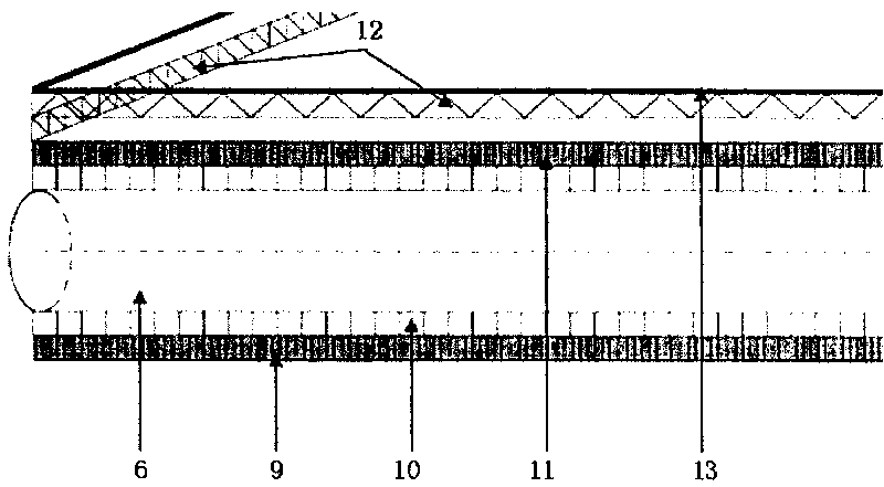
[0021] Such as figure 2 As shown, the structure and function of the backlight module 8 are similar to ...


PUM


Abstract

The invention provides a laser backlight surface light source which comprises a laser source, a beam-splitter mirror, a reflecting mirror, two beam expanding mirrors, two tiny light guide bars and a light guide plate, wherein the laser source is positioned in front of the beam-splitter mirror, and the reflecting mirror is arranged behind the beam-splitter mirror; the two beam expanding mirrors are respectively arranged at one side of the beam-splitter mirror and the reflecting mirror; the tiny light guide bars are embedded at the upper and the lower sides of the light guide plate and respectively positioned at one side of the two beam expanding mirrors; after being treated by light splitting and beam expanding, a laser beam passes through the two tiny light guide bars to form a cylinder or line light source evenly giving out light towards the side; and the light given out from the side of the tiny light guide bars enters the light guide plate for homogenizing light, so that the laser backlight surface light source can be formed. The light source has reasonable structure, and is far better than a backlight adopted by the existing liquid crystal display system in the aspects of color gamut range, color brightness degree and color fidelity when being used for liquid crystal display.

Description

technical field [0001] The invention relates to a laser backlight surface light source for a laser display system, belonging to the technical field of laser display. Background technique [0002] In recent years, the development of liquid crystal display (LCD) has advanced by leaps and bounds, and it occupies a very important position in the field of flat panel display. LCD TVs, notebook computers, mobile phones, etc. have entered thousands of households, and LCD monitors have become the mainstream monitors in the market today. This stems from the various advantages of liquid crystal displays: no radiation, low energy consumption, small heat dissipation, light and thin, and easy to carry. Most traditional liquid crystal displays use cold cathode fluorescent tubes (CCFL) as backlight sources, and their main defects are: [0003] 1. Cold cathode fluorescent tubes contain a small amount of mercury, which does not meet environmental protection standards; [0004] 2. Light lea...

Claims


Application Information

Patent Timeline
IPC IPC(8): F21S8/00F21V5/00F21V7/00F21V8/00F21V13/00F21V7/22G02F1/13357
Inventor 王玉荣丁海生王洪君宋刚李庆华张行愚连洁万强
Owner SHANDONG UNIV
Features
  • R&D
  • Intellectual Property
  • Life Sciences
  • Materials
  • Tech Scout
  • Unparalleled Data Quality
  • Higher Quality Content
  • 60% Fewer Hallucinations
Learn More