Closed fireplace with intake air distribution system

A distribution system and closed technology, which is applied in household stoves/stoves, lighting and heating equipment, solid heating fuels, etc., can solve the problems of low combustion efficiency, poor viewing effect, and large environmental pollution, and achieve large flame width and set Simple, less environmental pollution effect

Inactive Publication Date: 2010-05-05
朱宏锋 +1
View PDF2 Cites 4 Cited by
  • Summary
  • Abstract
  • Description
  • Claims
  • Application Information

AI Technical Summary

Problems solved by technology

[0003] The purpose of the present invention is to solve the problems of concentrated fuel, low combustion efficiency and great environmental pollution in existing fireplaces that use wood pellets as fuel, and provide a kind of fireplace with high combustion efficiency and low environmental pollution with an air inlet distribution system. closed fireplace
[0004] Another object of the present invention is to provide a fireplace with a large flame width, strong heat feeling and good viewing effect with an air inlet distribution system to solve the problems of concentrated flames, weak heat sensation and poor viewing effect existing in existing fireplaces. closed fireplace

Method used


Image

  • Closed fireplace with intake air distribution system
  • Closed fireplace with intake air distribution system
  • Closed fireplace with intake air distribution system

Examples


Embodiment 1

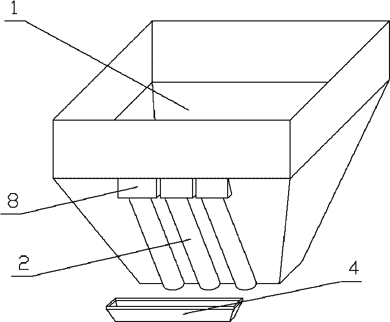
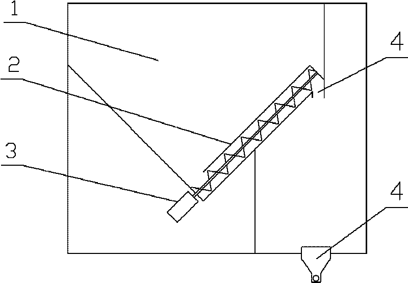
[0028] in such as figure 1 figure 2 In the shown embodiment 1, a closed fireplace with an air inlet distribution system includes a furnace, an air inlet and outlet system, and a hot blast system. The furnace is provided with a ventilation duct and a combustion chamber (not shown in the figure). The rear side is provided with a hopper 1 and a fuel conveying device 2. The front wall of the hopper 1 is the rear wall of the furnace, and the fuel conveying device is a parallel structure of three auger devices driven by motors 3, and is arranged on the bottom slope of the fireplace hopper. A blanking opening 8 is set on the furnace wall at the upper end of the auger. The bottom of the combustion chamber is provided with a furnace box 4, the furnace box is a long groove structure, its cross-section is trumpet-shaped, the bottom is provided with a heating rod 5, the two sides of the heating rod are air inlets 6, and the length of the furnace box is the length of the furnace. 50% of...

Embodiment 2

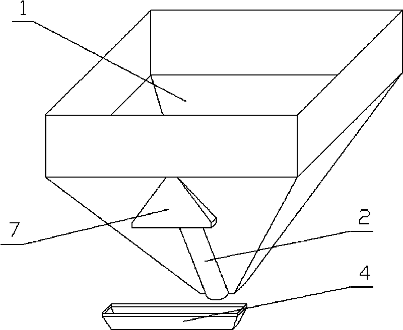
[0030] in such as image 3 Figure 4 In the shown embodiment 2, the furnace box is a long groove structure, the length of the furnace box is 60% of the furnace width, and the box wall of the furnace box is provided with 2 rows of secondary air inlet holes arranged horizontally (see Figure 6 ), respectively arranged on the upper and lower parts of the furnace box wall, and the distance between the air inlet holes near the middle of the strip-shaped furnace box is smaller than the air inlet holes at both ends of the furnace box. The air inlet hole is inclined to the bottom of the furnace box, and the included angle between the axis line of the air inlet hole and the bottom plane of the furnace box is 10 degrees. The fuel delivery device is a motor-driven auger device, and the outlet of the delivery device at the upper end of the auger is provided with a material distribution device 7 (see Figure 9 ), the material distribution device is a flat hollow structure, the feed port ...

Embodiment 3

[0032] There is only one row of air inlet holes on the furnace box of embodiment 3 (see Figure 7 ), set in the middle part of the furnace box wall, the length of the furnace box is 70% of the furnace width, the air inlet hole is inclined to the bottom of the furnace box, and the angle between the axis line of the air inlet hole and the bottom plane of the furnace box is 30 Spend. The distributing rods in the distributing device are set in layers and misplaced, and the distribution density of the distributing rods near the edges on both sides is greater than that in the middle (see Figure 11 ). All the other are identical with embodiment 2.

[0033] The hearth, furnace door, air inlet and outlet system, hot air system and fuel delivery device of the closed fireplace with air inlet distribution system are basically consistent with the existing technology, and the working principle and process of combustion and heating are also basically the same. Again, when the fireplace i...


PUM


Abstract

The invention discloses a closed fireplace with an intake air distribution system, comprising a heath, a combustion conveyor and a hot air system. The heath is internally provided with a ventilation pipeline and a combustion chamber; the bottom of the combustion chamber is provided with a fireplace box in long groove structure; the length direction of the fireplace box is identical with the width direction of the fireplace; the bottom of the fireplace box is provided with a heating rod both sides of which are provided with air inlets; and the box wall of the fireplace box is provided with a plurality of secondary air inlets. The invention effectively solves the problems of fuel integration, low combustion efficiency and great environmental pollution existing in the traditional fireplace using wood grains as fuel, also solves the problems of flame integration, unobvious heat feeling and poor viewing effect existing in the traditional fireplace, has great fireplace flame width, strong heat feeling, good viewing effect, high heat efficiency, little environmental pollution and notable economic benefits and social benefits.

Description

technical field [0001] The invention relates to a fireplace, in particular to a closed fireplace with an air inlet distribution system. Background technique [0002] The main structure of the existing fireplace is composed of a combustion chamber and a base. The opening is set on the combustion chamber, facing the indoor side. The top of the combustion chamber is provided with a waste gas outlet. When in use, the fuel is manually fed into the combustion chamber through the opening. Indoors, the heat generated by combustion is transferred to the room through natural radiation, which makes the indoor temperature rise. The disadvantage of this kind of fireplace is that the thermal efficiency is low, and the heat generated by burning wood is transferred through radiation. The exhaust gas is discharged to the outside; the second is that the safety is poor. In the case of poor ventilation, it is easy to cause indoor hypoxia. For this reason, fireplace manufacturers have developed...

Claims


Application Information

Patent Timeline
Patent Type & Authority Applications(China)
IPC IPC(8): F24B1/19F24B1/191
Inventor 朱宏锋王竹宏
Owner 朱宏锋
Why Eureka
Try Eureka