
Transparent armor system and method of manufacture

一种装甲、透明的技术,应用在装甲、装甲板的结构、化学仪器和方法等方向,能够解决剥离、透明装甲变色等问题

Inactive Publication Date: 2010-05-05
SCHOTT DIAMOND OBSERVATION ARMOR PROD LLC
View PDF0 Cites 11 Cited by
  • Summary
  • Abstract
  • Description
  • Claims
  • Application Information

AI Technical Summary

Problems solved by technology

The end result is that traditional transparent armor can discolour and peel off after long-term exposure to UV radiation, such as in long-term outdoor conditions

Method used


Image

  • Transparent armor system and method of manufacture
  • Transparent armor system and method of manufacture
  • Transparent armor system and method of manufacture

Examples


Embodiment Construction

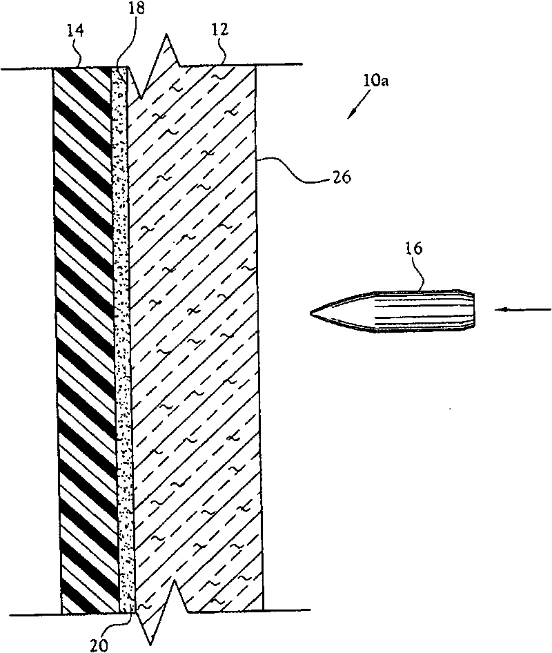
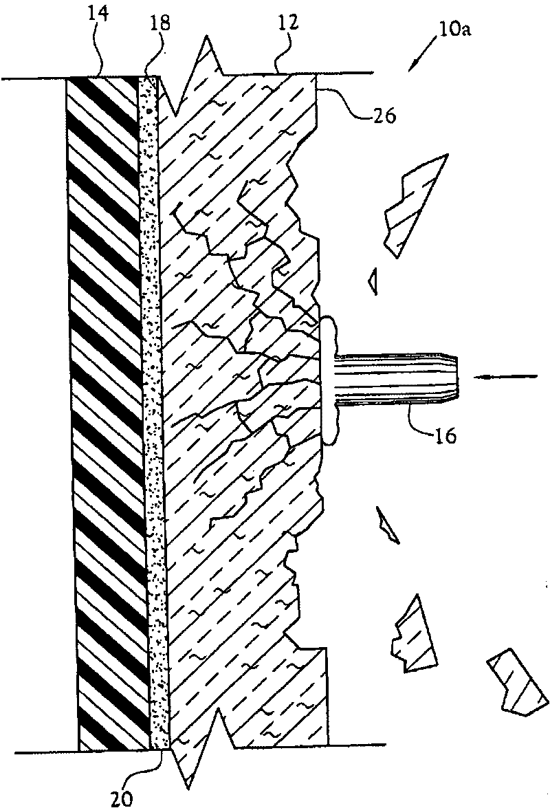
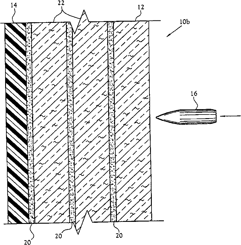
[0021] Disclosed herein is a transparent armor system for limiting the transmission of projectile impact forces and a corresponding method of manufacture. The transparent armor system is indicated generally at 10 in the Figures. refer to figure 1 , one embodiment of a transparent armor system 10a includes a hard layer 12 and a back layer 14 covering a rear surface 18 of the hard layer 12 that faces away from an incoming projectile 16 in anticipation.

[0022] The hard layer 12 is formed by a layer of glass-ceramic material having a hardness and compressive strength sufficient to substantially absorb at least a portion of the impact of an incoming projectile 16 . The hard layer 12 is formed with a front surface 26 configured to face the incoming projectile 16 and a rear surface 18 configured to face away from the incoming projectile 16 . It should be understood that the particular type of glass-ceramic material suitable for use in hard layer 12 depends on the mass, velocity ...


PUM


Abstract

A transparent armor system includes a hard face fabricated from a substantially transparent glass-ceramic material exhibiting crystalline bodies throughout the mass of the glass-ceramic material and a backing covering a rear surface of the hard face opposite an anticipated incoming projectile. The backing has a refractive index substantially matching that of the hard face such as to allow substantial transparency of the transparent armor system. In certain embodiments, a bonding layer is provided to bond the backing to the hard face. The hard face serves to disburse energy caused by the impact of an incoming projectile with the transparent armor system, while the backing serves to retain any pieces of the hard face fractured during ballistic impact.

Description

[0001] Cross References to Related Applications [0002] none applicable [0003] Statement on Federally Sponsored Research or Development [0004] none applicable technical field [0005] This invention relates to ballistic armor. More specifically, the present invention relates to a clear armor system employing a glass-ceramic hard layer that provides equivalent protection in ballistic armor construction while being lighter than most commercially available conventional clear armor and less expensive to manufacture than an equivalent weight clear system lower. Background technique [0006] In order to protect personnel and equipment from ballistic projectiles, explosive ordnance, and the explosive force and explosives from improvised explosive devices (collectively "shells"), it is necessary to provide a means of dissipating the kinetic energy of these projectiles to prevent these projectiles from reaching their goals. While this can be accomplished by interposing a...

Claims


Application Information

Patent Timeline
Patent Type & Authority Applications(China)
IPC IPC(8): F41H5/04
CPCB32B17/10036B32B17/10119B32B17/10761F41H5/0407B32B17/1077B32B17/10045F41H5/0428F41H5/0414
Inventor J·卡伯里G·D·福塞思K·莱顿
Owner SCHOTT DIAMOND OBSERVATION ARMOR PROD LLC
Learn More