Gear box of heavy CNC vertical turning machine

A digitally controlled vertical gearbox technology, which is applied to large fixed members, metal processing machinery parts, metal processing equipment, etc., can solve the problems of easy oil immersion, poor heat dissipation of motors, etc., and achieve low manufacturing cost, large driving force, The effect of high transmission stiffness

Inactive Publication Date: 2010-05-12
齐重数控装备股份有限公司
View PDF0 Cites 9 Cited by
  • Summary
  • Abstract
  • Description
  • Claims
  • Application Information

AI Technical Summary

Problems solved by technology

This design can not only avoid the interference between the motor and the largest workpiece, but also solve the problems of poor heat dissipation and oil immersion of the motor, so as to ensure the transmission efficiency and reduce the manufacturing cost

Method used


Image

  • Gear box of heavy CNC vertical turning machine
  • Gear box of heavy CNC vertical turning machine
  • Gear box of heavy CNC vertical turning machine

Examples


example 1

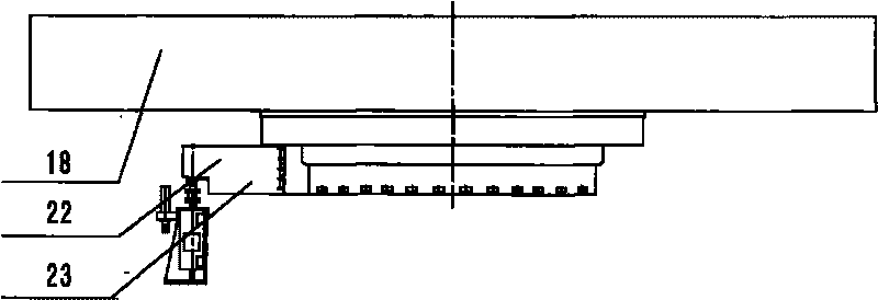
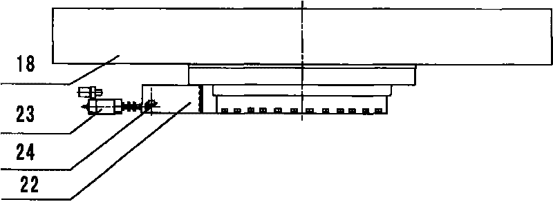
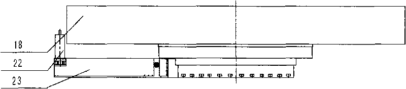
[0027] like Figure 4 As shown, the design includes the motor base 2, the box body 22 of the gearbox, the intermediate shaft in the box body 22, the intermediate gear mounted on the intermediate shaft, and the power input mechanism between the intermediate shaft and the motor 23, the intermediate shaft section The box body 22 of the motor seat 2 is stretched downward, and the box body 22 of the second section of the motor seat moves down synchronously. The intermediate gear on the intermediate shaft moves down, drives the power input mechanism between it and the motor base 2 and moves into the lower casing 4, and the height of the lower casing 4 is determined according to the height of the motor.

[0028] The intermediate shaft in this example is the upper case III shaft 9, and the lower end is connected with a lower case III shaft 7 through a spline coupling sleeve 8, and the input gear on the lower case III shaft 7 is connected with the power input mechanism between it and t...

example 2

[0030] The power output mechanism between the upper box III shaft 9 and the workbench base 11 is; the upper box III shaft 9 transmits power to the large ring gear through the output gear, IV shaft 10, V shaft 13, and VI shaft 15 in the workbench 17. 16. After the hydraulically controlled mechanical two-speed shift, it is transmitted to the workbench base 11.

[0031] The hydraulic mechanical two-speed transmission structure is driven by the shifting hydraulic cylinder 21 to move the shift fork 19 and the joint 12 to move up and down, respectively combined with the two-speed kinematic chain to realize two-speed transmission. When the joint 12 stops in the middle, it is in neutral. Used in conjunction with the C-axis, the gear shift position of the shift fork 19 is provided with a gear travel switch 20, and is provided with an in-position signal display device. See Figure 5 .


PUM


Abstract

The invention discloses a gear box of a heavy CNC vertical turning machine, which comprises a motor base, a gear box body, an intermediate shaft in the box body, an intermediate gear which is arranged on the intermediate shaft and a power input mechanism which is arranged between the intermediate shaft and the motor. The box body on the intermediate shaft section is stretched downwards, the box body on the motor base section moves synchronously, and the two sections of the box body are transversely jointed to form a step-shaped lower box body; and the lower end of the intermediate shaft is lengthened to reach into the lower box body, and the intermediate gear arranged on the intermediate shaft moves downwards to drive the power input mechanism arranged between the intermediate shaft and the motor base to move into the lower box body. The gear box of the heavy CNC vertical turning machine has the advantages of high precision, high transmission efficiency, high transmission rigidity, simple and compact structure, low manufacturing cost, low noise, high reliability and high driving force, can enable a worktable to realize a minimum speed of 0.15r / min, a maximum rotating speed of 125r / min and a torque of 1,000 kN.m, can be provided with a 50-160kW motor and has the capability of driving a ultra-large vertical lathe worktable with a bearable load of 1,000 tons.

Description

technical field [0001] The invention relates to a gearbox for a heavy-duty numerical control vertical lathe, which is suitable for installation on a single-column mobile vertical lathe, a workbench mobile vertical lathe, a double-column vertical lathe, and a double-column mobile vertical lathe with a large workpiece rotation diameter. use. Background technique [0002] For a long time, the maximum workpiece interference phenomenon of the motor of the heavy-duty CNC vertical lathe has been a very difficult problem. With the rapid development of my country's nuclear power industry, shipbuilding industry, mining, metallurgy and other heavy industries, the demand for large-scale vertical lathes is increasing in recent years, and the processing diameter of vertical lathes is also rapidly increasing to prevent the interference of the largest motor workpiece. Difficulty and importance are also increasing. At present, the research and development of the main gearbox of the large ve...

Claims


Application Information

Patent Timeline
Patent Type & Authority Applications(China)
IPC IPC(8): B23Q1/25
Inventor 焦建华石志民姜辉胡巍耿波杨文宽崔大龙卜明珠
Owner 齐重数控装备股份有限公司
Why Eureka
Try Eureka