Hydraulic control device of automatic transmission

A technology of automatic transmission and control device, which is applied in the direction of transmission device, gear transmission device, transmission device control, etc. It can solve the problems of excess oil pump flow, unsatisfactory performance, low efficiency, etc., and achieve the effect of reducing energy consumption

Active Publication Date: 2010-05-12
ZHEJIANG GEELY AUTOMOBILE RES INST CO LTD +1
View PDF3 Cites 18 Cited by
  • Summary
  • Abstract
  • Description
  • Claims
  • Application Information

AI Technical Summary

Problems solved by technology

[0004] Most of the electronically controlled transmission technologies that are still in use were developed in the 1990s, and some may be earlier. Due to the backwardness of hydraulic technology and control technology at that time, its performance gradually failed to meet the current needs, and its efficiency was low. .At the same time, the oil supply of the oil pump must meet the minimum pressure requirements and the minimum speed requirements that can produce the maximum oil pressure. Generally, the AT should determine its flow according to the flow requirements at low speeds. Therefore, when the engine rotates at high speeds, the oil pump flow is often excessive.

Method used


Image

  • Hydraulic control device of automatic transmission
  • Hydraulic control device of automatic transmission
  • Hydraulic control device of automatic transmission

Examples


Embodiment Construction

[0019] The following are specific embodiments of the present invention and in conjunction with the accompanying drawings, the technical solutions of the present invention are further described, but the present invention is not limited to these embodiments.

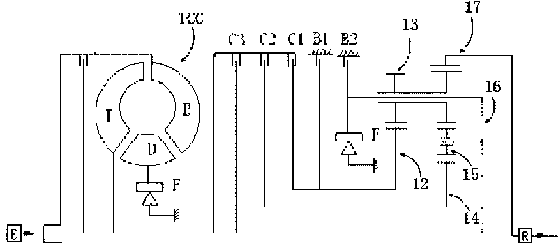
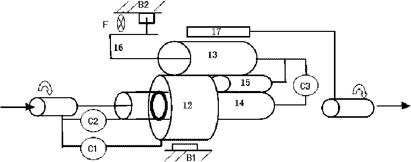
[0020] Such as figure 1 with figure 2 As shown, the transmission controlled by the hydraulic control device provided by the present invention is a 4-speed planetary gear transmission, including a shift control system and a transmission gear system, wherein the shift control system includes a front clutch C1, a rear clutch C2, and a terminal clutch C3 , brake one B1 and brake two B2 and a one-way wheel F; the transmission gear system is a Lavigne type planetary gear structure, consisting of a small sun gear 14, a large sun gear 12, three short planetary gears 15, and three long Composed of planetary gear 13, planetary carrier 16 and ring gear 17, the short planetary gear 15 meshes with the small sun gear 14, and the long ...


PUM


Abstract

The present invention provides a hydraulic control device of an automatic transmission, and belongs to the technical field of automotive transmission control. The hydraulic control device solves the problems that the conventional hydraulic control device of the transmission has low efficiency, and the oil pump flow is surplus when the rotating speed of the motor is high. The hydraulic control device of the automatic transmission comprises an electronic control system and a hydraulic source connected with the transmission through an oil line, wherein the hydraulic source is used for outputting working oil pressure; the oil line connecting the hydraulic source with the transmission is provided with a manual valve and an electromagnetic valve component in sequence; the electronic control system is connected with the electromagnetic valve component and is used for controlling the switching-on and switching-off of the electromagnetic valve component; the hydraulic source comprises an oil tank, and two or more hydraulic pumps; and an oil inlet of each hydraulic pump is connected with the oil tank, while an oil outlet is communicated with an input port of the manual valve. When the rotating speed of the motor is low, an oil pump and an electric pump can be selected to simultaneously supply oil so as to reduce energy consumption; and when the rotating speed of the motor is high, the electric pump is stopped, and the oil pump separately supplies the oil.

Description

technical field [0001] The invention belongs to the technical field of automobile transmission control, and relates to a hydraulic control device of an automatic transmission. Background technique [0002] The structure of using hydraulic pressure to control the speed change of the transmission has been well known in the past. In the case where the transmission is provided with a hydraulic control device for the speed change control, such a hydraulic control device is composed of an oil pump and a hydraulic control valve, which are arranged in the transmission case. , by selectively engaging a plurality of hydraulic engagement devices to achieve a plurality of gears having different gear ratios from each other. [0003] The mechanical structure of the commonly used 01N automatic transmission is mainly composed of 1 planetary gear set, 3 clutches, 2 brakes and 1 one-way wheel. The clutches are divided into front clutches, rear clutches and terminal clutches, and the brakes a...

Claims


Application Information

Patent Timeline
Patent Type & Authority Applications(China)
IPC IPC(8): F16H61/00F16H61/686
CPCF16H3/663
Inventor 李书福杨健赵福全陈勇尹宏声陈宗帖
Owner ZHEJIANG GEELY AUTOMOBILE RES INST CO LTD
Why Eureka
Try Eureka