
Oxygen-free surface water drying system and surface water drying technology for material

A technology of drying system and drying process, which is applied in the direction of heating to dry solid materials, drying solid materials, drying, etc., which can solve the problems of high drying cost and large power consumption, and achieve the effect of reducing energy consumption and emission

Inactive Publication Date: 2010-05-12
郑州拉姆顿清洁能源工程技术有限公司
View PDF0 Cites 6 Cited by
  • Summary
  • Abstract
  • Description
  • Claims
  • Application Information

AI Technical Summary

Problems solved by technology

Due to the problem of large power consumption in fluidized bed drying, the drying cost of the third-generation drying method is relatively high

Method used


Image

  • Oxygen-free surface water drying system and surface water drying technology for material
  • Oxygen-free surface water drying system and surface water drying technology for material
  • Oxygen-free surface water drying system and surface water drying technology for material

Examples


Embodiment 1

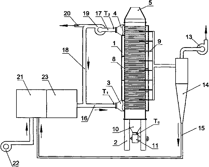
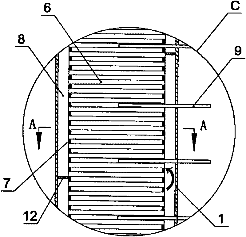
[0042] Embodiment one: see figure 1 , figure 2 , diagram 2-1 , Figure 2-2, a material surface water anaerobic drying system, including a drying device, a heating system 21, the drying device includes a vertical drying cylinder 7, the upper and lower ends of the drying cylinder are respectively provided with a coal inlet 5 and a coal outlet 10, and The lower part of the drying cylinder 7 is fixedly equipped with an air inlet pipe 16, and the upper part is fixedly equipped with an air outlet pipe 17; the outer sides of the two side walls of the vertical drying cylinder are respectively provided with a hot air chamber 8 that is isolated from the drying cylinder and independent of each other. A certain number of exhaust pipes 6 are connected between the hot air chambers, so that the material in the drying cylinder 7 is completely isolated from the hot air chamber 8 and the hot air in the exhaust pipes 6; Connected; the heating flue gas output pipe of the heating system is co...

Embodiment 2

[0052] Embodiment 2: The meaning is basically the same as that of Embodiment 1, and the similarities will not be repeated. The difference is: during the material drying process step, the flue gas input temperature T is controlled. 1 400~1200℃, flue gas output temperature T 2 100-300°C.

Embodiment 3

[0053] Embodiment 3: The meaning is basically the same as that of Embodiment 1, and the similarities will not be repeated. The difference is: in the process step of drying the material, the discharge rate of the material is controlled, and the final heating temperature T of the material is kept. 0 It is between 100 and 150°C.


PUM


Abstract

The invention relates to an oxygen-free surface water drying system and a surface water drying technology for material, wherein the oxygen-free surface water drying system comprises a drying device and a heating system; the drying device comprises a vertical drying cylinder and a coal inlet, a coal outlet, an air inlet pipe and an air outlet pipe which are arranged at the upper end and the lower end of the vertical drying cylinder; the outer sides of two side walls of the drying cylinder are respectively provided with a hot-gas cavity; a certain number of rack pipes or rack plates are communicated between the two hot-gas cavities to lead the coal in the drying cylinder to be completely separated from the hot gas in the hot-gas cavities and the rack pipes or the rack plates; the orifices of the air inlet pipe and the air outlet pipe are respectively provided with a thermograph T1 and a thermograph T2, a discharge hole is provided with a thermograph T0, a steam tube is arranged in the drying cylinder and led out of a drying device, drying is conducted at normal atmosphere, and the temperature of T1, T2 and T0 is controlled to remove the surface water of the material. The invention completely solves the problem of firing and explosion caused by combustible gas precipitation, is not only applicable to oxygen-free surface water drying of coal, but also applicable to the drying of chemical products, industrial and municipal sludge, metallic and nonmetallic minerals, coal slime and the like.

Description

1. Technical field: [0001] The invention relates to a material surface water drying and modification technology, in particular to a material surface water anaerobic drying system and a material surface water drying process. 2. Background technology: [0002] Coal Moisture Control (CMC for short) is the abbreviation of "Furnace Coal Moisture Control Technology". . CMC is different from coal preheating and coal drying. CMC has strict moisture control measures, which can ensure constant moisture content of coal entering the furnace. To reduce and stably control the moisture of the incoming coal through direct or indirect heating, instead of seeking to remove the moisture of the incoming coal to the greatest extent, but only to stabilize the moisture at a relatively low level, can achieve the purpose of increasing efficiency, and do not suffer from Too low moisture will cause difficulties in the operation of coke ovens and recovery systems, increase the density of coal in the ...

Claims


Application Information

Patent Timeline
Patent Type & Authority Applications(China)
IPC IPC(8): F26B17/12F26B3/18F26B23/10F26B25/22
Inventor 黄龙李英群查理德·迪玻特克里斯托夫·摩豪斯
Owner 郑州拉姆顿清洁能源工程技术有限公司
Learn More