Continuous remote transmission float type level gauge

A liquid level gauge and float type technology, which is applied in the field of liquid level measurement, can solve the problems of difficulty in assembly and calibration, easy deposition of condensate, and increase the quality of the float, and achieves easy assembly, debugging and calibration, structure and secondary instruments. The effect of simplicity and improved measurement accuracy

Inactive Publication Date: 2010-05-12
DALIAN CONSERVATION SCI & TECH CO LTD
View PDF19 Cites 8 Cited by
  • Summary
  • Abstract
  • Description
  • Claims
  • Application Information

AI Technical Summary

Problems solved by technology

Its advantage is that there is no friction caused by magnetic coupling force, but its disadvantages are: 1. The signal is discontinuous
2. The electric guide rail is immersed in the liquid. It must be made of corrosion-resistant materials, and it cannot be used in explosion-proof occasions. When running up and down, the brush will carry the medium from the guide rail to the float.
3. There is an aging problem in the elastic insulating ring, which affects reliable use
5. The power supply to the spotlight and the power supply to the photosensitive element belong to two circuits, and the float measurement and photosensitive element parts are independent, that is, the magnetic float uses pulleys and tracks, and the remote sensor uses a set of fixed brackets, resulting in a complex structure
6. Roller pulleys and spotlights are placed on the float, which further increases the quality of the float, and then needs to increase the volume and thickness of the float and the float chamber shell. In this case, it is not suitable for low-density and high-pressure applications.
7. It is easy to form water film on the surface of the spotlight or gather dust on the photosensitive element, which will affect the use
10. There are many internal parts in the float chamber shell. When it is used in strong corrosive media, all the internal parts must be made of expensive corrosion-resistant materials, resulting in increased costs.
[0008] As described in ZL99220056.3, ZL94235895.3, ZL200820107045.9, ZL94206404.6, and ZL89210466.X, they have the following problems respectively: 1. The structure is complex and huge, the transmission mechanism has many wire wheels, and the friction is large, which affects the accuracy and sensitivity
2. The on-site instructions are not clear and visual inspection is difficult, especially at night or in darkness
3. Some have no remote transmission or the remote transmission signal is not continuous
4. Cumulative errors caused by slipping
5. On-site instruction and remote transmission use two independent mechanisms, resulting in complex structure and high cost
[0009] As described in ZL200410015416.7, this liquid level gauge can solve the application of high-pressure boilers, but it has the following shortcomings: 1. Two structural parts or fixed frames are used for on-site indication and remote transmission, which makes the structure complicated. 2. Remote The transmission signal is discontinuous. 3. The magnetic car needs 4 wheels, otherwise the cursor will deflect or shake up and down and cannot be used. This will make the structure complicated, and the second will increase the weight of the magnetic car, thereby increasing the load of the float, which is quite Due to the increase in the weight of the float, it is difficult to meet the use in high temperature and high pressure or high pressure and low density medium occasions. 4. On-site visual inspection is inconvenient. 5. The float and the float chamber are sliding friction, the friction force is large, and the display lags behind.
[0010] As mentioned in ZL89210640.9, the liquid level gauge uses rolling friction to reduce the frictional force. Its disadvantages are: 1. The signal remote transmission part needs to add a sliding wire resistor with a skeleton and the sliding wire resistor. The movable arm makes the structure complex and additionally increases the friction
2. Although it is mentioned that the float is simple in spherical shape, when the float is made of non-ferromagnetic material, ferromagnetic material is embedded in the water line (liquid level line) or equatorial zone, which will form sliding friction and cause large friction force. It can be seen that the The inventor only considered the simple manufacture of spherical floats, coupled with inlaying ferromagnetic materials on the waterline or equatorial zone and mentioned sliding friction descaling, it can be seen that the inventor did not consider the influence of the shape of the float on friction
But there are the following shortcomings: 1. The float is open, and the condensate is easy to deposit inside the float, which affects normal use
2. The structure is complicated, and a lot of parts are used only for the clear display on site
3. At the same time, there are some problems listed in the aforementioned ZL200410015416.7
In addition, the reed switch signal is discontinuous, unreliable, and the circuit is complicated
[0013] As described in ZL97243163.2, its advantage is that the on-site instructions are clear, but there are still the following shortcomings: 1. Two pairs of static contacts are used to connect different light-emitting diodes, so that there are many switches and light-emitting elements, which affects reliability.
2. More components and more complex structure
3. The signal is not continuous
[0014] 2. Existing float-type liquid level gauges with no local indication but remote transmission
[0015] As described in ZL99203851.0 and ZL02215560.0, their advantages are simple in structure, and their disadvantages are: 1. The sensing element is inserted into the tube extending in the container liquid, which is not resistant to high temperature
2. The float with a guide hole in the middle is not resistant to high pressure
3. Another set of connecting pipes is required if the local indication is realized
4. The float is easy to get stuck
5. Use reed switch to make more components, unreliable and discontinuous signal
6. Two spiral tube type resistance wires are adjacently wound on the insulator, too dense is easy to short circuit, too sparse will affect the accuracy
When the winding is too loose, it may not work properly due to the point contact of the ball and the disconnection
7. It is possible to stop work during maintenance
[0016] As mentioned in ZL98229246.5: Its advantage is that it does not require magnetic sensitive components, which greatly improves reliability, but it also has the following disadvantages: 1. The resistor is placed in the sensor tube, which cannot be used in high temperature applications
2. The float and shell of this structure are not resistant to high pressure (the internal pressure of the tube is greater than the external pressure)
3. The weight of the float increased by the magnetic trolley is not conducive to the use in high temperature and high pressure or high pressure and low density occasions
4. The signal is not continuous
5. There is no on-site instruction, if additional on-site instructions are added, an additional set of institutions is required
6. The structure of the magnetic trolley is complex
[0020] 1. The remote transmission signal is not continuous;
[0021] 2. There are many precious metals or corrosion-resistant materials (pulleys, bearings, float chambers, etc. need to be selected according to process conditions, such as high temperature and corrosion), which further increases the manufacturing cost;
[0022] 3. Higher working pressure or high pressure and low density occasions are difficult to apply;
[0023] 4. The counterweight (or counterweight) is immersed in the liquid to affect the accuracy;
[0024] 5. Difficulty in assembly and calibration;
Some structures are huge, which increases the burden of packaging and transportation;
[0026] 7. There are many friction pairs or there is sliding friction between the float and the pipe wall, resulting in high friction (steel-to-steel sliding friction coefficient μ is 0.15, steel-to-steel cylindrical radial rolling friction coefficient is 0.05, spherical steel balls to steel The coefficient of friction is less than 0.003
[0030] 9. The structure is complex, such as on-site indication and remote transmission need two sets of mechanisms, other complex mechanical mechanisms, etc., large size, poor reliability, high cost
[0031] 10. The float or float chamber needs to be made very long, which wastes materials, is huge in size, and has a heavy burden on packaging and transportation
[0032] 11. The float is easy to get stuck

Method used


Image

  • Continuous remote transmission float type level gauge
  • Continuous remote transmission float type level gauge
  • Continuous remote transmission float type level gauge

Examples


Embodiment 1

[0099] Embodiment 1: Float type liquid level gauge for atmospheric pressure vessel

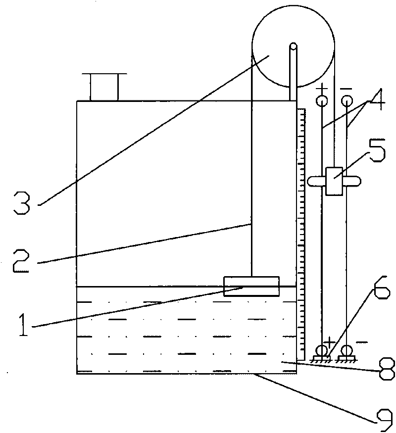
[0100] like figure 1 , the float type liquid level gauge shown in 2 includes a float 1, a connecting rope or a connecting belt 2 placed on the pulley 3, and its two ends are respectively connected with the float 1 and the magnetic coupling 5, and are fixed perpendicular to the ground on an insulating fixed Two magnetically conductive and electrically conductive guide rails 4 on the block 6, and the pulley 3 are fixed above the container 9.

[0101] The two guide rails 4 are fixed by the insulating block 6 under them, and at least one of them is covered with an insulating layer and wound with a resistance wire;

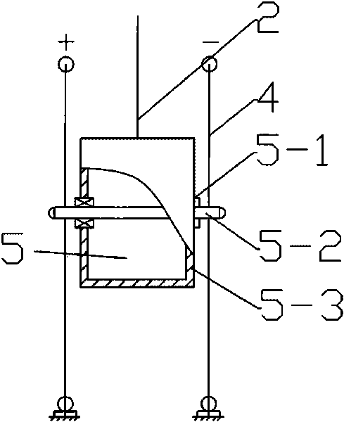
[0102] The magnetic coupling 5 is located between the two guide rails 4, and includes an insulating box 5-3 and a horizontally arranged magnetic shaft 5-2; bearings 5-1 are respectively installed in the holes on the two side plates of the insulating box 5-4; The two ends of the magne...

Embodiment 2

[0107] Embodiment 2: A float type liquid level gauge for a pressure vessel

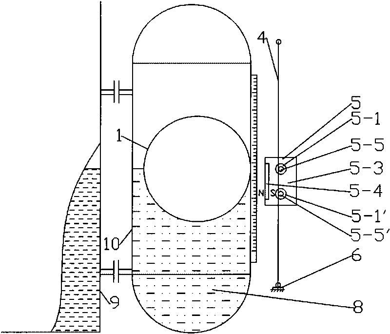
[0108] like image 3 , the float type liquid level gauge shown in 4 comprises a float chamber 10 made of a non-ferromagnetic material that communicates with the measured container 9 and is fixed on the measured container 9, and a float 1 made of a ferromagnetic material in the float chamber 10, It is characterized in that it also includes two guide rails 4 outside the float chamber 10, an insulating block 6 under the guide rails 4 and a magnetic coupling 5, and the magnetic coupling 5 is located between the two guide rails 4, including an insulating box 5-3, The magnetic steel 5-4 and the metal shaft 5-5 arranged horizontally; the magnetic steel 5-4 is located on the side close to the float 1 in the insulating box 5-3, and its magnetic pole is facing the float 1; similar to embodiment 1, the insulation Bearings 5-1 are respectively installed in the holes on the two side plates of the box 5-3; the met...

Embodiment 3

[0116] Example 3: A magnetic float level gauge suitable for pressure vessels with medium temperatures that are not too high

[0117] In the case where the temperature of the medium is not too high, that is, when the magnetic steel will not be demagnetized, in order to increase the magnetic attraction force, a magnetic float type liquid level gauge is used, such as Figure 5 , shown in 6, differs from embodiment 2 in that: its float 1 is made of non-ferromagnetic material, and more than one piece of circular magnetic steel A11 with the same inner diameter as the float is housed in the float, and on the magnetic coupling 5, two guide rails 4 More than 1 circular magnetic steel B5-6 is housed between them, the magnetic steel B5-6 is a circular magnetic steel, and the center of the magnetic steel B5-6 has a hole, which is fixed with the metal shaft by the hole. The magnetic steel B5-6 is fixed in the central part of the insulating box 5-3, the magnetic poles of the magnetic steel ...


PUM


Abstract

The invention relates to a continuous remote transmission floater type level gauge, which comprises a floater and a magnetic connector, the continuous remote transmission floater type level gauge is characterized in that: the level gauge further comprises an electrically conductive or magnetically inductive and electrically conductive guide rail, and at least one guide rail is covered by an insulating layer and wound with resistance wires; the magnetic connector comprises an insulating case and a magnetic shaft or a metal shaft arranged horizontally; for the magnetic floater type level gauge, the magnetic connector further comprises a magnetic steel; the magnetic shaft or the metal shaft moves up and down along the guide rail with the up-and-down movement of the floater under the action of magnetic force; and a corresponding liquid level value is obtained by measuring a resistance value in a conducting loop consisting of the guide rail, the magnetic shaft or the metal shaft so as to realize continuous remote transmission of liquid level data. The continuous remote transmission floater type level gauge can further comprise a fixed slide pulley, a balance weight, a connecting rope or a balancing magnetic connector brought by connection. The continuous remote transmission floater type level gauge has remarkable characteristics of simple structure and continuous remotely transmitted signal.

Description

technical field [0001] The invention relates to the field of liquid level measurement, in particular to a continuous remote transmission float type or magnetic float type liquid level gauge. Background technique [0002] The liquid level gauge is an instrument with a wide range of applications, and many people study the problems existing in the prior art. [0003] Existing liquid level measuring instruments are of various types, each with its own strengths, but also have shortcomings. Based on the present invention, the existing instruments have unclear on-site indications, are difficult to observe in dark places or at night, and remote signals are not clear. Continuous, remote transmission and local indication use two sets of mechanisms, and a series of problems such as large friction affecting measurement accuracy, etc., the existing comparative technologies are described as follows: [0004] - Existing local indicating type and / or additional float type liquid level gauge...

Claims


Application Information

Patent Timeline
Patent Type & Authority Applications(China)
IPC IPC(8): G01F23/46
Inventor 王嘉贤王媛媛刘勇刘秋实纪永祥
Owner DALIAN CONSERVATION SCI & TECH CO LTD
Why Eureka
Try Eureka