Inclined fluorescence excitation and detection light path device

A detection optical path, fluorescence detection technology, applied in the direction of fluorescence/phosphorescence, material excitation analysis, etc., can solve the problem of easy entry of excitation light into the detection optical path, reducing the signal-to-noise ratio of the detection signal, unfavorable fluorescence signal detection, etc., to improve the signal-to-noise ratio. , The effect of uniform light intensity distribution and simple position adjustment

Inactive Publication Date: 2010-05-12
FUJIAN NORMAL UNIV
View PDF0 Cites 3 Cited by
  • Summary
  • Abstract
  • Description
  • Claims
  • Application Information

AI Technical Summary

Problems solved by technology

In the coaxial state, the width of the excitation light beam is equivalent to the width of the sample chamber cross-section in the Y-axis direction; in the orthogonal state, the excitation light beam is equivalent to the width of the sample chamber cross-section in the X-axis direction; on each particle; the disadvantage of the coaxial optical path system is that the reflected or transmitted strong light signal of the excitation light on the sample and the sample chamber is easy to directly enter or reflect into the detection optical path, even if the cut-off filter is often used to completely cut off this signal. Strong light, which will cause strong interference to the fluorescent signal and greatly reduce the signal-to-noise ratio of the detection signal, which is not conducive to the detection of the fluorescent signal
Although the optical path system with the orthogonal distribution of the excitation light path and the detection light path overcomes the shortcoming of the coaxial light path structure, in order to obtain the strongest fluorescent signal, the sample chamber often uses the side with the wider side of the cross section to face the detection light path, and the orthogonal The distributed excitation optical path is perpendicular to the narrower side of the cross-section of the sample chamber. Due to the manufacturing process of the sample chamber, the bending of the narrow side of the cross-section of the glass sample chamber is serious. Therefore, the optical path system with the orthogonal distribution of the excitation optical path and the detection optical path The excitation light incident from the narrow side causes beam deformation and serious scattering, which is not conducive to the control of the experiment, and the more serious scattering excitation light is easy to enter the detection optical path, reducing the signal-to-noise ratio of the detection signal, which is not conducive to the detection of fluorescence signals

Method used


Image

  • Inclined fluorescence excitation and detection light path device
  • Inclined fluorescence excitation and detection light path device

Examples


Embodiment Construction

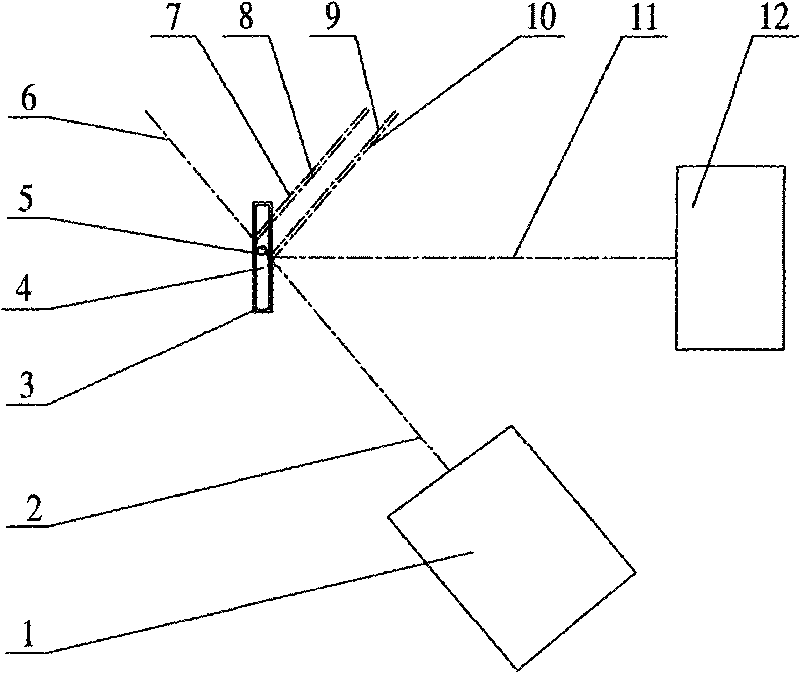
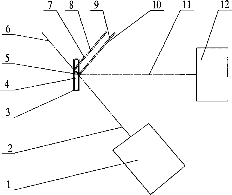
[0007] The structure of the present invention comprises a sample chamber (3), an excitation light generator (1), and a fluorescence detection device (12). One side is orthogonal, and the width of the excitation light beam is not less than the width covering the field of view on the object side of the microscope. It is characterized in that: the excitation light generator (1) is placed obliquely on one side of the sample chamber (3), and the excitation light generator (1) The excitation light path and the detection light path of the fluorescence detection device (12) intersect at the center of the cross-section of the sample chamber (3) at an acute angle, and the following conditions are met: the intersection angle between the excitation light path and the detection light path is any angle between 20° and 70°, this The inclination angle should ensure that the excitation light does not directly enter the fluorescence detection optical path, and ensure that the reflected light of ...


PUM


Abstract

The invention provides an inclined fluorescence excitation and detection light path device, which relates to a fluorescence excitation and detection device. The device comprises a sample room, an exciting light generator and a fluorescence detection device, wherein a detection light path faces one surface with a wider cross section side length of the sample room and is orthogonal with the surface, and the width of an exciting light beam is not less than that of a viewing field covering a microscopic object side. The inclined fluorescence excitation and detection light path device is characterized in that the exciting light generator is inclined on one side of the sample room, an excitation light path of the exciting light generator is in acute angle intersection with a detection light path of the fluorescence detection device in the center of the cross section of the sample room, and the following conditions are met: the intersection angle of the excitation light path and the detection light path is between 20 and 70 degrees, and the inclination angle ensures that the exciting light does not enter the fluorescence detection light path and also ensures that the reflected light of the exciting light does not enter the fluorescence detection device. The inclined fluorescence excitation and detection light path device has the advantages of effectively preventing the exciting light from entering a fluorescence signal detection device through transmission and reflection, reducing scattered exciting light to enter the fluorescence signal detection device and to cause strong interference light to the utmost extent, and greatly improving the noise-signal ratio of detection; and the integral form and position adjustments of the exciting light are simpler.

Description

Technical field: [0001] The invention relates to a fluorescence excitation and detection device, and is especially suitable for a fluorescence excitation and detection optical path device in the flow cytometry detection technology. Background technique: [0002] At present, the fluorescence excitation and detection devices of the flow cytometry technology that can detect the size, variety, and quantity of flow cells in the fluid use excitation light to perform fluorescence excitation on the sample in the transparent sample flow chamber, and the sample chamber often uses a cross-section It is a rectangular transparent conduit; if the liquid flow in the conduit is the positive direction of the Z axis, the symmetry axis of the long side direction of the rectangular cross section of the sample chamber is the Y axis, and the vertical line forming the plane of the Z axis and the Y axis is the X axis, The optical path of the detection receiver coincides with the X axis. The detect...

Claims


Application Information

Patent Timeline
Patent Type & Authority Applications(China)
IPC IPC(8): G01N21/64
Inventor 王敏梁秀玲张万祯卓金寨
Owner FUJIAN NORMAL UNIV
Why Eureka
Try Eureka