Detection device of laser damage threshold of optical crystal element

A technology of laser damage threshold and optical crystal, which is used in measurement devices, material analysis by optical means, scientific instruments, etc., can solve the problem of accurate measurement of laser damage threshold without optical crystal components, and achieve reliable clamping and accurate damage point. The effect of accurate observation and precise movement

Inactive Publication Date: 2010-05-12
HARBIN INST OF TECH
View PDF0 Cites 17 Cited by
  • Summary
  • Abstract
  • Description
  • Claims
  • Application Information

AI Technical Summary

Problems solved by technology

[0003] The purpose of the present invention is to solve the problem that there is no special detection device to realize the accurate test of the l

Method used


Image

  • Detection device of laser damage threshold of optical crystal element
  • Detection device of laser damage threshold of optical crystal element
  • Detection device of laser damage threshold of optical crystal element

Examples


specific Embodiment approach 1

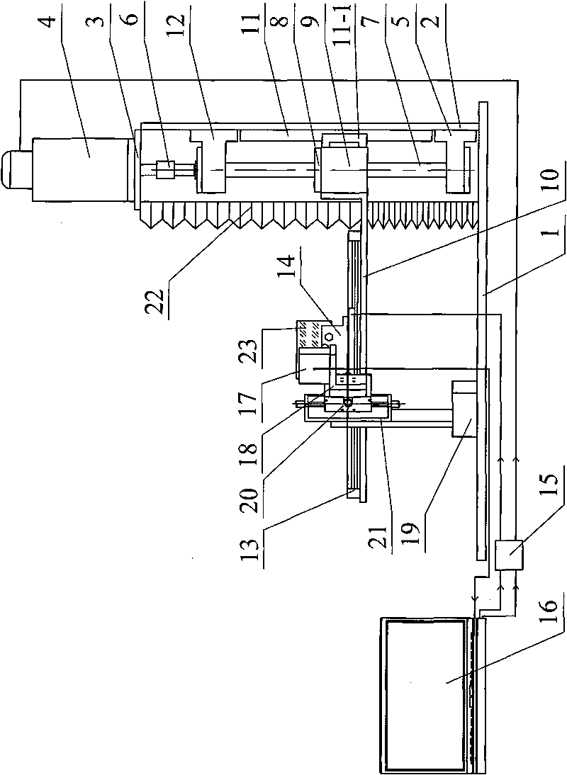
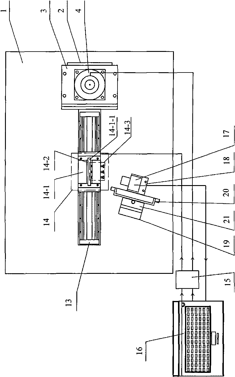
[0012] Specific implementation mode one: the following combination figure 1 , figure 2 , Figure 5-Figure 8 and Figure 17-Figure 21 To illustrate this embodiment, this embodiment includes a horizontal table 1, a motor support frame 2, a motor connecting plate 3, a servo motor 4, a lower bearing assembly 5, a shaft coupling 6, a ball screw 7, a ball screw nut 8, a wire Female slider 9, L-shaped linear motor support plate 10, linear guide rail 11, upper bearing assembly 12, flat linear motor 13, optical element clamp body 14, two-axis motion control card 15, control computer 16, CCD camera 17, L-shaped CCD connection plate 18, CCD support frame 19, horizontal micro-displacement workbench 20 and vertical micro-displacement workbench 21,

[0013] The bottom end of the motor support frame 2 is centered and fixed on one side of the upper surface of the horizontal workbench 1, the top end of the motor support frame 2 is fixedly connected with the motor connection plate 3, the se...

specific Embodiment approach 2

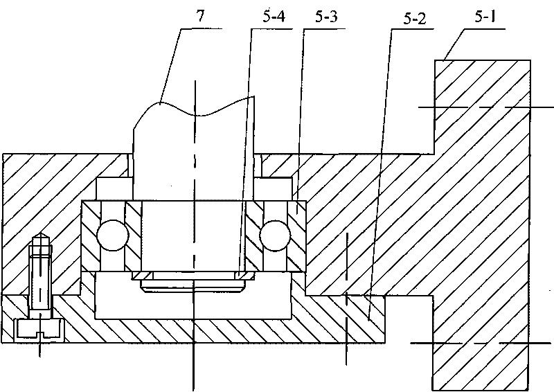
[0038] Specific implementation mode two: the following combination image 3 and Figure 4 To illustrate this embodiment, the difference between this embodiment and Embodiment 1 is that the lower bearing assembly 5 consists of a lower bearing seat 5-1, a lower bearing cover 5-2, a sealed angular contact thrust ball bearing 5-3 and a shaft The end retaining ring is composed of 5-4,

[0039] The lower bearing seat 5-1 of the lower bearing assembly 5 is fixed at the middle position of the lower end of an inner surface of the motor support frame 2, the lower bearing cover 5-2 is fixedly connected with the lower bearing seat 5-1, and the sealed angular contact thrust ball bearing 5 The inner ring of -3 is matched and fixed with the lower end of the ball screw 7 through the shaft end retaining ring 5-4, and the outer ring of the sealed angular contact thrust ball bearing 5-3 is passed through the lower bearing seat 5-1 and the lower bearing cover 5-2 Cooperate and fix, there is a g...

specific Embodiment approach 3

[0040] Specific implementation mode three: the following combination Figure 9 and Figure 10 To illustrate this embodiment, the difference between this embodiment and Embodiment 2 is that the upper bearing assembly 12 is composed of an upper bearing housing 12-1, an upper bearing cover 12-2, and two sealed angular contact thrust balls dedicated to ball screws. Bearing 12-3 and round nut 12-4 are formed,

[0041] The upper bearing seat 12-1 of the upper bearing assembly 12 is fixed on the middle position of the upper end of one inner surface of the motor support frame 2, the upper bearing seat 12-1 is fixedly connected with the upper bearing cover 12-2, and the two ball screws are specially sealed Angular contact thrust ball bearings 12-3 are set facing to each other and are connected and fixed. The inner rings of the two ball screw special-purpose sealed angular contact thrust ball bearings 12-3 are fixed by the ball screw 7 and the round nut 12-4. The two ball screws The o...


PUM


Abstract

The invention relates to a detection device of a laser damage threshold of an optical crystal element, belonging to the technical field of laser damage threshold detection of optical crystal elements and solving the problem that no special detection device realizes the accurate testing of the laser damage threshold of the optical crystal element at present. The detection device controls the motion of a servo motor and a flat linear motor by controlling computer programming so that an initial testing area of the optical crystal element is positioned on a path of a laser beam; the relative position between a CCD camera and the optical crystal element is adjusted through a vertical micro-displacement work table and a horizontal micro-displacement work table; the rotation motion of the servo motor is transformed into the linear motion of a ball nut through a ball screw, and the ball nut drives a nut slide block to move up and down so as to drive a support plate of an L-shaped linear motor to move up and down, thus the flat linear motor can adjust the height of a clamp body of the optical crystal element up and down. The invention is used for the detection of the laser damage threshold of the optical crystal element.

Description

technical field [0001] The invention relates to a laser damage threshold detection device for an optical crystal element. Background technique [0002] As an important way to solve energy problems, inertial confinement fusion (ICF) has been paid more and more attention by governments of various countries. The solid-state laser in the ICF device needs to output a very high-energy beam in the final stage to achieve the ignition of the deuterium-tritium pellet, so there are high requirements for the laser damage threshold of various crystal components used to make the laser. For example, KH 2 PO 4 (Potassium Dihydrogen Phosphate, referred to as: KDP) crystals are often made into Pockels cells or optical frequency doubling components and are widely used in ICF engineering, requiring their laser damage threshold ≥ 15J / cm 2 . At present, the measured laser damage threshold of KDP crystals is much lower than its required value. In order to explore ways to increase the laser da...

Claims


Application Information

Patent Timeline
IPC IPC(8): G01N21/84
Inventor 陈明君李明全姜伟姜文斌陈宽能
Owner HARBIN INST OF TECH
Why Eureka
Try Eureka