Preparation method of common pole-type thin film solar cell

A technology of thin-film solar cells and common electrodes, applied in circuits, photovoltaic power generation, electrical components, etc., can solve problems such as forced cooling of solar cells and temperature rise of solar cells, and achieve increased short-circuit current density, increased replacement efficiency, and stability Good results

Inactive Publication Date: 2011-06-01
JIANGSU UNIV
View PDF0 Cites 0 Cited by
  • Summary
  • Abstract
  • Description
  • Claims
  • Application Information

AI Technical Summary

Problems solved by technology

However, in order to ensure that the focal spot converges on the concentrating cell, the concentrator and the concentrating cell need to be installed on a sun tracking device, and the sun needs to be tracked, which requires adding additional power, control devices and strict wind resistance measures to the system. ; At the same time, when working under high light intensity, the temperature of the concentrating thin film solar cell will rise significantly, and at this time the solar cell must be forced to cool down

Method used


Image

  • Preparation method of common pole-type thin film solar cell
  • Preparation method of common pole-type thin film solar cell
  • Preparation method of common pole-type thin film solar cell

Examples


Embodiment Construction

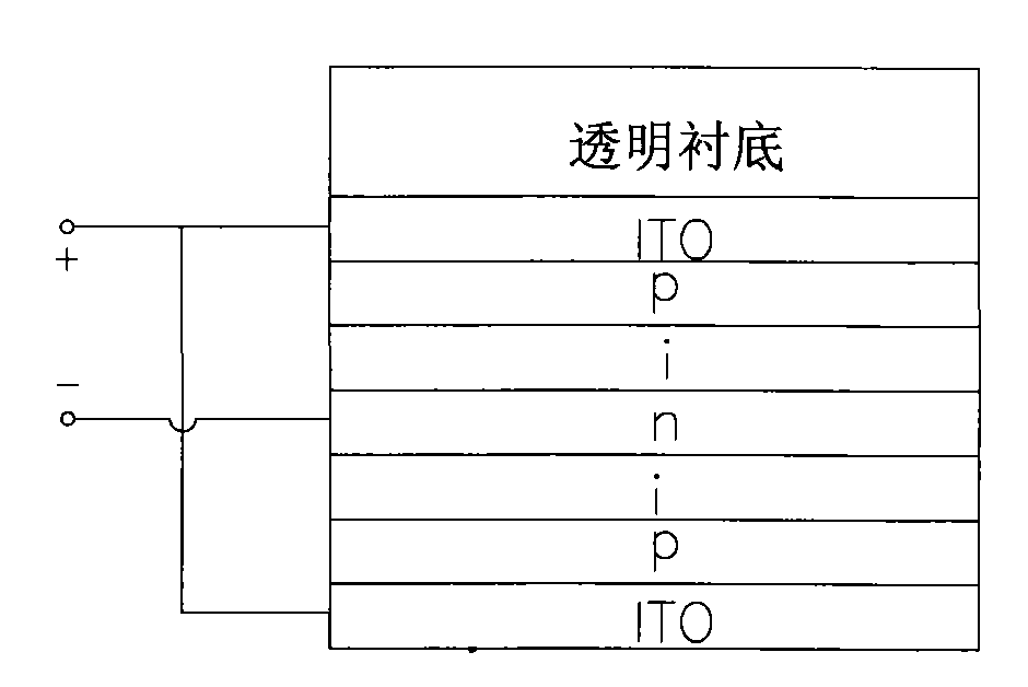
[0020] 1. Structural design of solar cells

[0021] Design p on transparent substrate + / p / i / n / i / p / p + Structured common-pole thin-film solar cells. Increase P + It is to reduce the contact resistance, increase the short-circuit current and open-circuit voltage; at the same time, the direct lead-out electrode of the n-layer avoids the large-area contact between the n-layer and the metal electrode. p + / p / i / n and other layers of optical band gap E g Gradually decreasing, it can effectively expand the spectral absorption range; at the same time, it also has a certain inhibitory effect on the formation of the incubation layer during film preparation, thereby increasing the open circuit voltage and fill factor.

[0022] 2. Preparation of common electrode thin film solar cells

[0023] Hereinafter, the present invention takes nano-silicon as an example to illustrate the preparation of a copolar thin-film solar cell.

[0024] 2.1 Cleaning of transparent substrate

[0025] 1....


PUM


Abstract

A common pole-type thin film solar cell relates to the fields of thin film technology and new energy development technology, and consists of a glass substrate, an ITO transparent electrode, a p layer (p+ and p), an i layer, an n layer, the i layer, the p layer (p and p+) and the ITO electrode from a bottom layer to a top layer; a lead wire is led out from the upper ITO transparent electrode layerand the lower ITO transparent electrode layer as a common electrode and is taken as an anode, and the lead wire led out from the n layer is taken as an cathode. The common pole-type thin film solar cell has good stability, light acceptance at two sides, low internal resistance loss, high conversion efficiency, high filling factor and good I-V characteristic.

Description

technical field [0001] The invention relates to the field of thin-film technology and new energy development technology, and uses thin-film materials to prepare thin-film solar cells with a novel double-sided light-receiving structure, in particular to a common-pole thin-film solar cell. Background technique [0002] Since the first amorphous silicon thin-film solar cell came out in the 1970s, the advantages of less power consumption, low water consumption, and material cost are only 1% of bulk silicon materials have been unanimously approved by authorities in the same industry at home and abroad. And known as "the first generation of solar cells." On this basis, the second-generation thin-film solar cells have realized large-area production with cheap materials such as ordinary glass, plastic, and stainless steel sheets as substrates. In recent years, in order to further improve the problems existing in the first and second generation solar cells, continue to reduce costs ...

Claims


Application Information

Patent Timeline
Patent Type & Authority Patents(China)
IPC IPC(8): H01L31/042H01L31/075H01L31/0352H01L31/18H01L31/0445H01L31/076
CPCY02E10/50Y02E10/548Y02P70/50
Inventor 丁建宁郭立强程广贵袁宁一
Owner JIANGSU UNIV
Why Eureka
Try Eureka