Method for continuously and thermally galvanizing pipe

A technology of hot-dip galvanizing and steel pipe, applied in hot-dip galvanizing process, coating, metal material coating process, etc., which can solve the problems of non-continuous production, waste of double-sided galvanizing, and difficulty in controlling the thickness of the coating, so as to improve automation Degree, reduce production cost, improve the effect of coating quality

Inactive Publication Date: 2010-05-19
BEIJING STAR RIVER INTEGRATED EQUIP TECH
View PDF4 Cites 7 Cited by
  • Summary
  • Abstract
  • Description
  • Claims
  • Application Information

AI Technical Summary

Problems solved by technology

[0002] At present, some of the original domestic galvanized pipes are produced by electroplating, and some are welded by galvanized sheets. The galvanized pipes are galvanized by electro-galvanizing. The thickness of the coating is difficult to control, the coating is thin, the production speed is slow, and the cost is high. Most of the hot-dip galvanizing adopts the cage dip galvanizing method. The steel pipe is cut into the required length, placed in the cage and immersed in a zinc pot. In this way, the zinc layer is coated on both sides, but the actual application is only The outer surface of the steel pipe needs to be galvanized, and the waste of double-sided galvanizing is serious; in addition, the welding process of the galvanized sheet is to roll-form the hot-dip galvanized sheet and weld it. Repair galvanized layer at weld seam
Galvanized on steel pipes, the production efficiency of these methods is low, continuous production is not possible, the process is complicated, and the labor intensity is high

Method used


Image

  • Method for continuously and thermally galvanizing pipe

Examples


Embodiment Construction

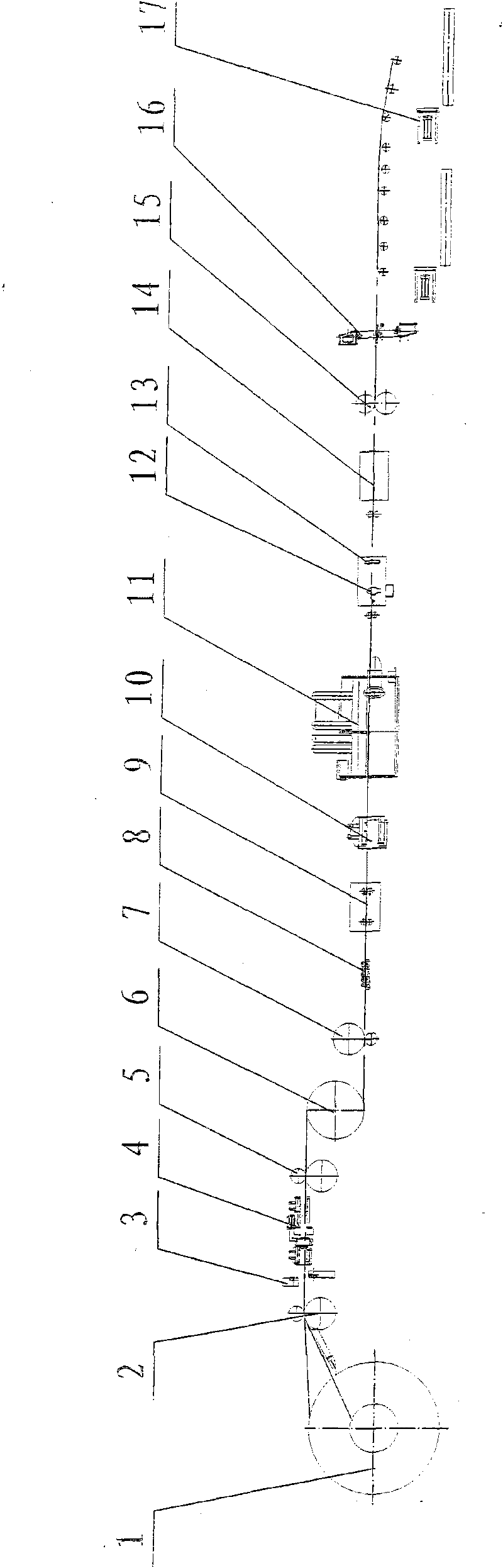
[0017] Entrance section: first place the steel coil on the uncoiler 1 with the steel coil car, cut off the plate head with the head and tail cutter 2, and flatten through the first pinch roller 3 and pass through the steel plate welding machine 4, and the previous one The steel coil is welded together by cutting the head and tail and cutting off the irregular tails of the steel plate, and changing the position and direction of the steel strip through the pinch roller 5, so that the steel strip enters the disc looper from the horizontal direction to the vertical direction. 6. The steel strip enters the coiled looper 6. When the coil is uncoiled normally, the coiled looper 6 stores the material. When the coil is changed and welded, the coiled looper 6 discharges the material, which meets the requirements of continuous production of the unit; the process section: the steel strip from The disc looper 6 comes out and is turned by the second pinch roller 7, so that the steel strip ch...


PUM


Abstract

The invention provides a method for continuously and thermally galvanizing a pipe. In the method, the whole process is completed continuously on line, a hot-rolled steel plate is used as a raw material plate, the whole processing process of the steel strip from unrolling to welding a steel pipe, to galvanizing and to shearing is completed on line, and the fully continuous and automatic production of the thermally galvanized pipe integrates unrolling, leveling, rolling, welding, cleaning, blowing with cold wind, specified length shearing and stacking. The method comprises the following steps: delivering the hot-rolled steel strip to a welding stage; delivering the welded continuous steel strip to a disk loop material storing and leveling stage; delivering the welded continuous steel strip to a rolling stage to longitudinally weld a steel pipe; delivering the steel pipe formed by rolling and welding to a zinc bath 12, and controlling the thickness of a zinc layer by using an annular air blade 13; delivering the galvanized steel pipe to a shearing and stacking stage and delivering the galvanized steel pipe to a specified length follow-up shears 16 to shear the steel pipe by required length; and stacking the steel pipes according to a required height with two stacking machines of which one is spared for later use. Production efficiency is improved and cost and expenses are saved.

Description

technical field [0001] The invention belongs to the field of galvanizing in the metallurgical industry, in particular to the production field of hot-dip galvanizing. Background technique [0002] At present, some of the original domestic galvanized pipes are produced by electroplating, and some are welded by galvanized sheets. The galvanized pipes are galvanized by electro-galvanizing. The thickness of the coating is difficult to control, the coating is thin, the production speed is slow, and the cost is high. Most of the hot-dip galvanizing adopts the cage dip galvanizing method. The steel pipe is cut into the required length, placed in the cage and immersed in a zinc pot. In this way, the zinc layer is coated on both sides, but the actual application is only The outer surface of the steel pipe needs to be galvanized, and the waste of double-sided galvanizing is serious; in addition, the welding process of the galvanized sheet is to roll-form the hot-dip galvanized sheet an...

Claims


Application Information

Patent Timeline
Patent Type & Authority Applications(China)
IPC IPC(8): C23C2/38C23C2/06
Inventor 汪为健
Owner BEIJING STAR RIVER INTEGRATED EQUIP TECH
Why Eureka
Try Eureka