
Current transformer and current detection system

A current transformer and current detection technology, applied in the direction of measuring current/voltage, voltage/current isolation, instruments, etc., can solve the problems of stability and accuracy error rate, and achieve stable working conditions and good test results

Inactive Publication Date: 2010-05-19
SOUTH CHINA NORMAL UNIVERSITY
View PDF0 Cites 10 Cited by
  • Summary
  • Abstract
  • Description
  • Claims
  • Application Information

AI Technical Summary

Problems solved by technology

[0006] In view of the problems existing in the above-mentioned prior art, an embodiment of the present invention provides a current transformer and a current detection system, through the design of a dual fiber grating transformer, it solves the problem of stability and accuracy error rate in the measurement process in the prior art The problem

Method used


Image

  • Current transformer and current detection system
  • Current transformer and current detection system
  • Current transformer and current detection system

Examples


Embodiment Construction

[0013] The embodiment of the present invention provides a current transformer and a current detection system, through the design of the dual fiber grating transformer, the problems of stability and accuracy error rate in the measurement process in the prior art are solved. .

[0014] Preferred embodiments of the present invention will be described in detail below in conjunction with the accompanying drawings.

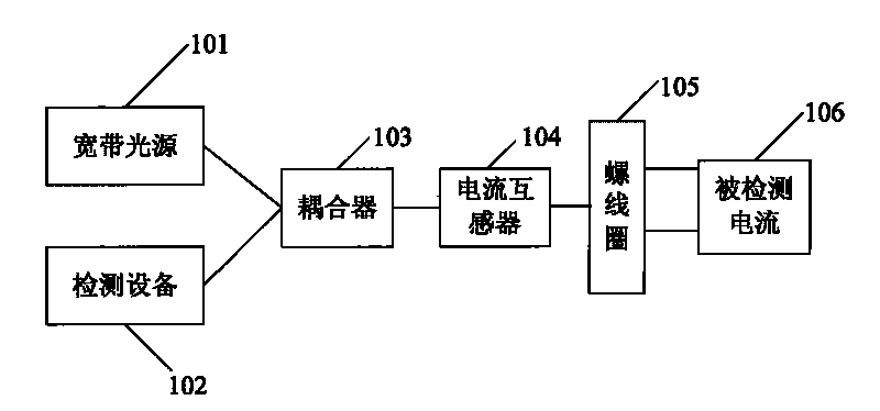
[0015] See first figure 1 , figure 1 It shows a schematic structural diagram of the current detection system in the implementation of the present invention. The current detection system includes a broadband light source device 101, a detection device 102, a current transformer 104, a coupler 103, and a detected current 106, wherein: the current transformer 104 Used to sense the current signal of the detected current 106, the broadband light source device 101 is used to provide a broadband light source to the current transformer. The current transformer 104 here inclu...


PUM


Abstract

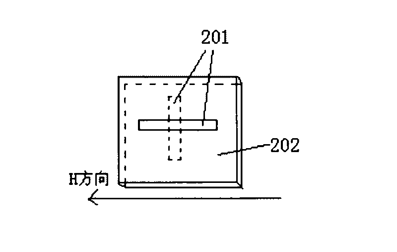
The invention discloses a current transformer with a sensing head which comprises a giant magnetostrictive material and two fiber gratings, wherein the fiber gratings are respectively positioned at the upper surface and the lower surface of the giant magnetostrictive material and are intercrossed at different surface layers of the giant magnetostrictive material. The invention further discloses a current detection system; according to the embodiment of the invention, linear, efficient and stable working state of the giant magnetostrictive material and the fiber gratings is acquired by means of temperature compensation via two fiber gratings, and the test result is good.

Description

technical field [0001] The invention relates to the field of electronic applications, in particular to a current transformer and a current detection system. Background technique [0002] Optical current transformers can be divided into active type and passive type according to whether the transformer part needs power supply. Passive type is a photoelectric current measuring device that does not have a power supply for the transformer part. It uses optical elements as current sensing elements. When external information interacts with light waves propagating in the optical medium, certain parameters of the light waves will be changed (such as Intensity, frequency, wavelength, phase or polarization state, etc.), that is, use this parameter to modulate the external information. At present, intensity-modulated, phase-modulated and polarization-modulated passive photoelectric current transformers have come out. However, due to the stability and reliability of the optical compone...

Claims


Application Information

Patent Timeline
Patent Type & Authority Applications(China)
IPC IPC(8): G01R19/00G01R15/14G01B11/16
Inventor 熊建文张准洪应娇左菁
Owner SOUTH CHINA NORMAL UNIVERSITY
Learn More