Permanent-magnetic AC reactor current restrictor

An AC reactance and permanent magnet technology, applied to emergency protection circuit devices, electrical components, circuit devices, etc. for limiting overcurrent/overvoltage, can solve short-circuit faults that cannot respond quickly, increase power loss, and system power Increased power consumption and other issues, to achieve the effect of simple structure, reduced cost, and enhanced reliability

Inactive Publication Date: 2010-05-19
HEBEI XUHUI ELECTRIC
View PDF1 Cites 12 Cited by
  • Summary
  • Abstract
  • Description
  • Claims
  • Application Information

AI Technical Summary

Problems solved by technology

Although this patent successfully solves the electromagnetic pollution of the reactor, when the reactor works normally, the iron core is in an unsaturated state, which virtually increases the power loss

Method used


Image

  • Permanent-magnetic AC reactor current restrictor
  • Permanent-magnetic AC reactor current restrictor

Examples


Embodiment Construction

[0022] The present invention will be described in further detail below in conjunction with the accompanying drawings.

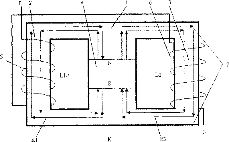
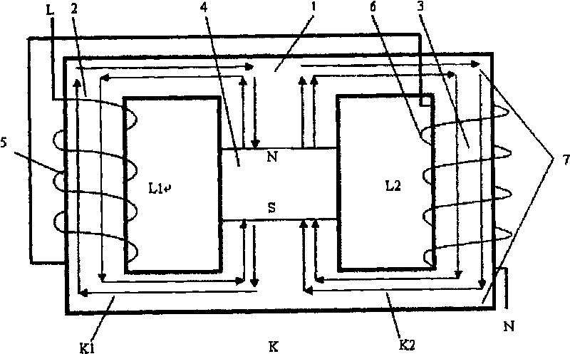
[0023] figure 1 It is a permanent magnet AC reactor type current limiter, including a reactance bridge. The reactance bridge is mainly composed of an AC winding, an iron core and an upper and lower iron yoke 7. The iron core includes a central column 1, left and right side columns 2, 3, and a central column A permanent magnet 4 is arranged inside, and an AC winding is set on the side column, and the AC winding is composed of two sets of AC coils 5, 6 with the same names in reverse series, and the coils are respectively set on the left and right columns 2, 3. The cross-sectional areas of the side columns 2 and 3 are equal, and the cross-sectional area of ​​the central column 1 is the sum of the cross-sectional areas of the left and right side columns 2 and 3.

[0024] The AC winding, the side column, the middle column, the upper and lower iron yokes and the c...


PUM


Abstract

The invention discloses a permanent-magnetic AC reactor current restrictor, which comprises a reactance bridge circuit and a permanent magnet, wherein the reactance bridge circuit mainly comprises an iron core, an upper iron yoke, a lower iron yoke and an AC winding; the iron core comprises a central pillar and a side pillar; the side pillar is sleeved with the AC winding; the AC winding is formed by serially connecting the same-named ends of AC coils in a reverse direction; the permanent magnet is arranged in the central pillar; the side pillar and the central pillar of the iron core, the upper iron yoke, the lower iron yoke and the middle-arranged permanent magnet form an AC magnetic field loop and a bias magnetic field loop. The current restrictor has the advantages of simple structure and reliable operation. When the current restrictor is applied to AC systems, the current restrictor can effectively reduce reactive power loss and voltage drop during normal operation, and can quickly respond to short circuit faults and effectively suppress short circuit current.

Description

technical field [0001] The invention relates to a short-circuit fault current limiter applied in an AC power system. Background technique [0002] With the increasing capacity of the power grid in the power system, the short-circuit current of the system is also greatly enhanced, and the short-circuit current formed by the short-circuit fault has become one of the most prominent problems that endanger the safe operation of the power system. At present, the power system generally adopts series reactors to limit short-circuit current, or connects large-capacity high-speed switches in series with reactors in parallel, or adopts new short-circuit fault current limiters. Both traditional reactors and high-speed switching devices have serious defects that limit the application of these two methods. The existing new short-circuit fault current limiter overcomes the shortcomings of the first two current limiting devices, but there are still some deficiencies. 1. Superconducting fa...

Claims


Application Information

Patent Timeline
IPC IPC(8): H02H9/02
Inventor 张旭辉王苏于云霞
Owner HEBEI XUHUI ELECTRIC
Why Eureka
Try Eureka