Ultra wide band cavity filter

A cavity filter, ultra-wideband technology, applied in the field of filters, can solve problems such as insertion loss and parasitic passband shortage

Inactive Publication Date: 2010-05-26
成都赛纳赛德科技有限公司
View PDF2 Cites 1 Cited by
  • Summary
  • Abstract
  • Description
  • Claims
  • Application Information

AI Technical Summary

Problems solved by technology

Most of the existing ultra-wideband filters adopt microstrip structure, which has deficiencies in insertion loss and parasitic passband

Method used


Image

  • Ultra wide band cavity filter
  • Ultra wide band cavity filter

Examples


Embodiment

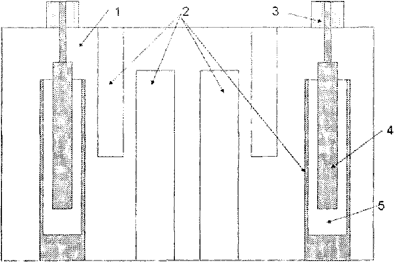
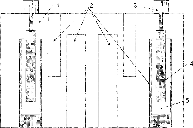
[0018] Such as figure 1 As shown, the ultra-wideband cavity filter includes a cavity 1, a resonant metal column 2 arranged in the cavity 1, and two input-output structures 3 arranged on the cavity 1, and the number of the resonant metal columns is six, The two input and output structures 3 are respectively provided with an inner conductor entering the cavity 1 , and the front end of each inner conductor extends into a resonant metal column 2 .

[0019] The resonant metal column 2 containing the inner conductor is provided with a cylindrical groove 5 , and the front end of the inner conductor extends into the groove 5 .

[0020] The front end of the inner conductor is also provided with a cylindrical coupling metal column 4 , which has a gap with the side wall and the bottom surface of the groove 5 . The coupling metal post 4 is wrapped around the front end of the inner conductor and is insulated from the inner conductor.

[0021] Among all the resonant metal pillars 2 , four...


PUM


Abstract

The invention discloses an ultra wide band cavity filter, belonging to the field of microwave communication and mainly solving the problems of band width and insertion loss of a traditional filter in the prior art. The ultra wide band cavity filter comprises a cavity, resonance metal columns and two input and output structures, wherein the resonance metal columns are arranged in the cavity; and the input and output structures are arranged on the outer wall of the cavity. The ultra wide band cavity filter is characterized in that the number of the resonance metal columns is at least two; the input and output structures are respectively provided with an inner conductive body entering the cavity; and the front end of each inner conductive body extends into the inner part of one resonance metal column. The ultra wide band cavity filter has the advantages of simple structure, convenient processing and installation and high utilization value.

Description

technical field [0001] The invention relates to a filter, in particular to an ultra-wideband cavity filter. Background technique [0002] UWB communication is one of the focuses of current research in academia and industry. Ultra-wideband communication needs to use ultra-wideband filtering. Specifically, it requires an ultra-wideband filter with a relative bandwidth of more than 20%, an in-band insertion loss of less than 1dB, and a parasitic passband outside twice the center frequency of the passband. Most of the existing ultra-wideband filters adopt microstrip structure, which has shortcomings in insertion loss and parasitic passband. Contents of the invention [0003] The purpose of the present invention is to provide an ultra-wideband cavity filter, which solves the shortcomings of the prior art, and reduces the in-band insertion loss on the basis of increasing the bandwidth of the filter. [0004] In order to achieve the above object, the technical solution adopted ...

Claims


Application Information

Patent Timeline
IPC IPC(8): H01P1/207
Inventor 廖翱王清源任屹灏
Owner 成都赛纳赛德科技有限公司
Why Eureka
Try Eureka