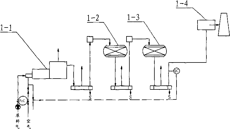
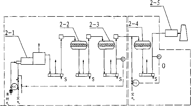
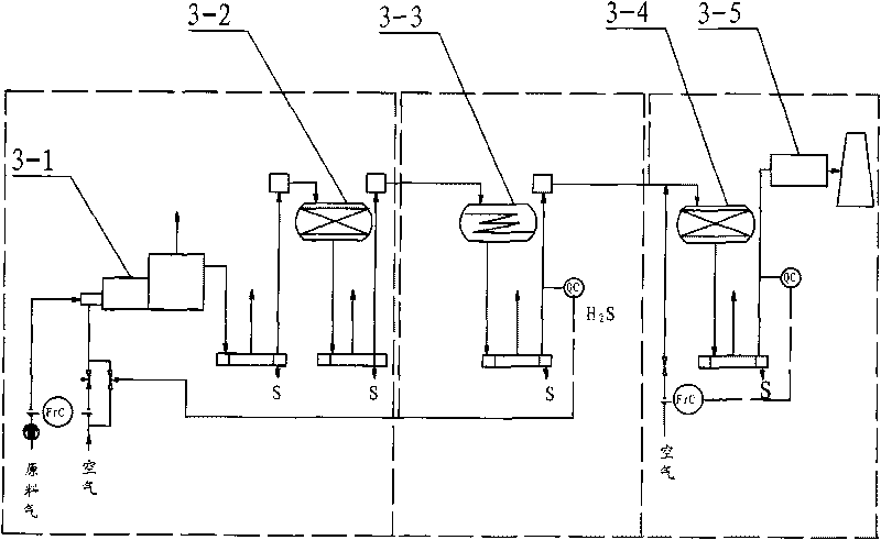
Double selectivity efficient sulfur recovery device

A sulfur recovery and selective technology, applied in the preparation/purification of sulfur, can solve the problems of high operating cost, large floor space and large investment, and achieve the effect of reducing operating cost, saving land area and reducing investment.

Inactive Publication Date: 2010-06-02
SHANDONG QILU PETROCHEM ENG
View PDF0 Cites 7 Cited by
  • Summary
  • Abstract
  • Description
  • Claims
  • Application Information

AI Technical Summary

Problems solved by technology

Tail gas emissions cannot meet the increasingly stringent sulfide content requirements, and sulfur tail gas treatment must be configured, such as SCOT process, etc.
This results in a substantial increase in investment and operating costs
[0008] The conventional improved Claus process, due to the following three problems, the total sulfur recovery rate is limited
[0009] (1) Claus reaction is a reversible equilibrium reaction, H 2 S and SO 2 cannot be completely transformed;
[0010] (2) Since the dew point of water is lower than that of sulfur, the water generated in the reaction cannot be removed from the process gas by simple methods, thereby hindering the conversion reaction and limiting the recovery rate of sulfur;
[0011] (3) Due to the fluctuation of the upstream device, the acid gas flow rate and H 2 The fluctuation of S concentration, it is difficult to control the H 2 S: SO 2 2:1
[0032] (1) Although the total sulfur recovery rate reaches 99.5%, it still cannot stably meet my country's emission standards;
[0033] (2) Tail gas still needs to be discharged after incineration;
[0034] (3) The reducing hydrogenation catalyst has a high service temperature and poor selectivity;
[0035] (4) The use temperature of the direct oxidation catalyst is 210-220°C higher, and the conversion rate is lower (90%);
[0036] (5) Claus+Scot process, although the total sulfur recovery rate is high (99.96%), but the investment is large, the floor area is large, the energy consumption is high, and the operating cost is high

Method used


Image

  • Double selectivity efficient sulfur recovery device
  • Double selectivity efficient sulfur recovery device
  • Double selectivity efficient sulfur recovery device

Examples


Embodiment

[0064] Such as Figure 4 As shown, a dual-selective high-efficiency sulfur recovery device includes sequentially connected in series combustion furnace and waste pot 4-1, primary Claus reactor 4-2, secondary Claus reactor and selective hydrogenation reactor 4-3. Three-stage selective oxidation reactor 4-4, deep desulfurization reactor 4-5, chimney 4-6;

[0065] Fill the peroxygen protection type and organosulfur hydrolysis type Claus catalyst in the primary Claus reactor 4-2;

[0066] In the two-stage Claus reactor 4-3, two different catalysts are loaded in two stages, and the Claus catalyst is loaded in the upper stage to continue the Claus reaction The lower section is loaded with a highly selective direct hydrogenation reduction catalyst, and the unreacted SO in the upper layer is 2 Direct hydrogenation reduction to elemental sulfur instead of H at a lower temperature of 200-220°C 2 S.

[0067] A low-temperature selective direct oxidation catalyst is loaded in the thre...


PUM


Abstract

The invention relates to a double selectivity efficient sulfur recovery device, belonging to the technical field of sulfur recovery. The device comprises a primary Claus reactor, a secondary Claus reactor and a third Claus reactor connected sequentially in series, and is characterized in that in the secondary Claus reactor, two different catalysts are filled in two sections, a Claus reaction catalyst is filled in the upper section, and a high selectivity direct reduction hydrogenation catalyst 1 is filled in the lower section; SO2 is hydrogenated and reduced into elemental sulfur by the reduction hydrogenation catalyst at 200-220 DEG C; a low-temperature selectivity direct oxidation catalyst is filled in the third Claus reactor; and H2S is selectively oxidized into elemental sulfur by the low-temperature selectivity direct oxidation catalyst. The device of the invention has high conversion rate of the H2S and less investment and does not need to strictly control the ratio of H2S / SO2 as 2:1 nor control H2S / SO2 to be larger than 2 / 1 as in the Super Claus process. Even the H2S is excess, the invention can adapt to larger changes of the acid gas flow rate and the H2S concentration caused by the fluctuation of an upstream device.

Description

technical field [0001] The invention relates to a method for purifying contained H from petrochemical and natural gas (or oilfield gas) 2 The technology for recovering sulfur from S acid gas is specifically a dual-selective high-efficiency sulfur recovery device. Background technique [0002] With my country's new environmental protection emission standards (national standard GB16927-1996 "Comprehensive Emission Standards for Atmospheric Pollutants"), SO 2 As content restrictions become increasingly stringent, for gas purification processes, the problem of using high-efficiency sulfur recovery and tail gas treatment technologies to increase sulfur recovery becomes more prominent. [0003] H 2 The Claus process of converting S into elemental sulfur is a patented technology invented by British chemist Carl Friedich Claus in 1883. Since then, the technology has undergone a series of improvements, called the modified Claus process, and is widely used in many countries. Such ...

Claims


Application Information

Patent Timeline
Patent Type & Authority Applications(China)
IPC IPC(8): C01B17/04
Inventor 胡宗敏胡文宾高红珍殷培国王刚
Owner SHANDONG QILU PETROCHEM ENG
Why Eureka
Try Eureka