
Spiral pyrolysis reactor

A technology of pyrolysis reactor and spiral, applied in the direction of direct heating dry distillation, special form dry distillation, petroleum industry, etc., can solve the problems of large size, large heat loss, difficult adjustment of reaction time, etc., and achieve simplified structure and process flow, sealing The effect of good performance and excellent working performance

Active Publication Date: 2010-06-02
SHANDONG UNIV OF TECH
View PDF0 Cites 14 Cited by
  • Summary
  • Abstract
  • Description
  • Claims
  • Application Information

AI Technical Summary

Problems solved by technology

In order to ensure sufficient reaction time, the reaction tube must have a sufficient length, so the size of the downtube reactor is relatively large, the circulation device of the heat carrier is also increased, and the heat dissipation loss is also large.
In addition, the reaction time of the downtube reactor is determined by the length and angle of the reaction tube, and the reaction time is difficult to adjust

Method used


Image

  • Spiral pyrolysis reactor
  • Spiral pyrolysis reactor
  • Spiral pyrolysis reactor

Examples


Embodiment Construction

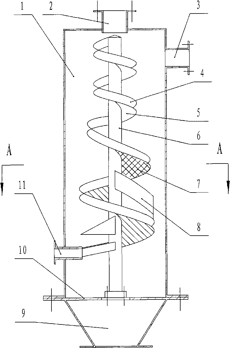
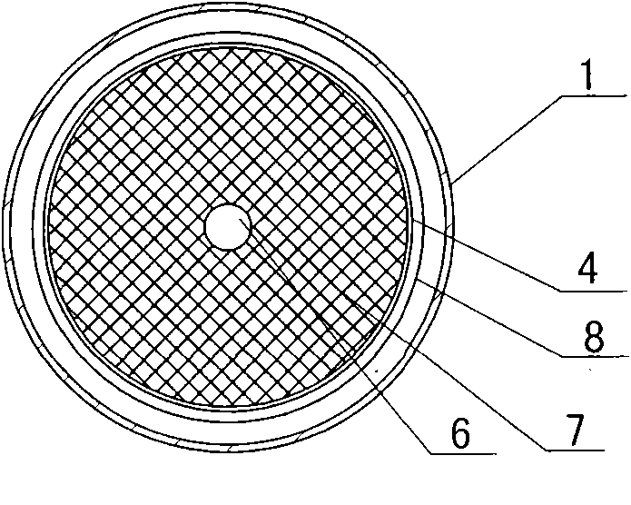
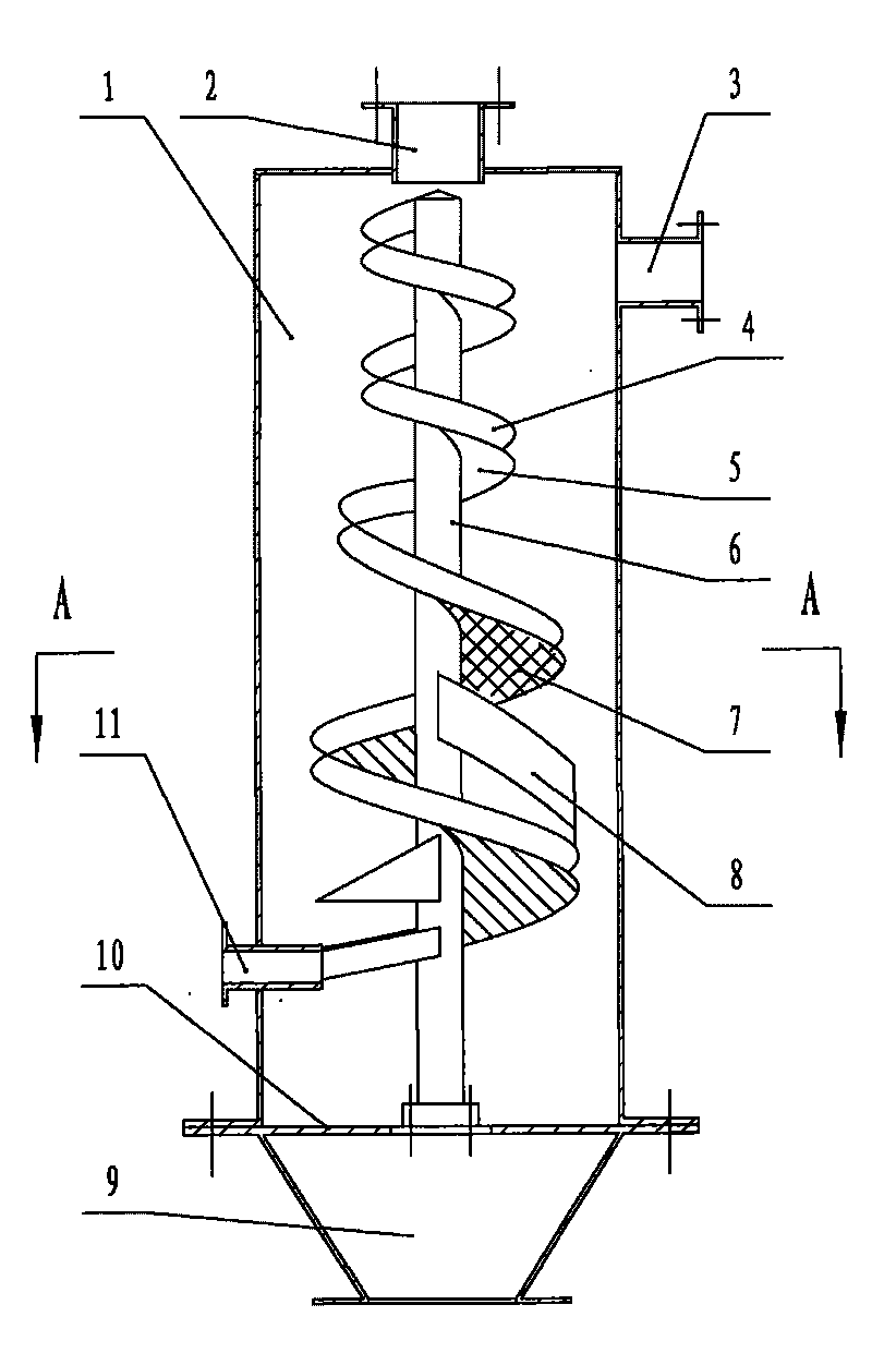
[0016] Including the shell 1, the top center of the shell 1 is provided with a feed inlet 2, the side wall of the upper end is provided with a pyrolysis gas outlet 3, the side wall of the lower end is provided with a heat carrier outlet 11, and the bottom is provided with a carbon powder outlet 9 A vertical shaft 6 is fixed in the center of the housing 1 and below the feed port 2 , and the bottom of the vertical shaft 6 is fixed in the center of the housing 1 via a bracket 10 . A spiral baffle 4 with gradually larger diameter is set on the vertical shaft 6, and a spiral bottom plate 5 is fixed and sealed between the bottom of the spiral baffle 4 and the vertical shaft 6 upwards from the middle of the vertical shaft 6, and downwards from the middle of the vertical shaft 6. A spiral screen 7 is fixed between the bottom and the vertical shaft 6. The spiral baffle 4 forms a bottom-sealed and bottom-unsealed spiral slideway with the spiral bottom plate 5 and the spiral screen 7 resp...


PUM


Abstract

The invention provides a spiral pyrolysis reactor comprising a shell, a material inlet, a pyrolysis gas outlet, a heat carrier outlet and a powdered carbon outlet. The spiral pyrolysis reactor is characterized in that a vertical shaft is fixed in the center of the shell; a spiral baffle plate whose diameter becomes larger gradually is sleeved on the vertical shaft; a spiral bottom plate is fixed and sealed between the bottom of the spiral baffle plate and the vertical shaft from the middle-upper part of the vertical shaft; a spiral sieve mesh in fixed between the bottom of the spiral baffle plate and the vertical shaft from the middle-lower part of the vertical shaft; a spiral slideway is formed by the spiral baffle plate, the spiral bottom plate and the spiral sieve mesh; the upper end of the spiral slideway is supported at the bottom of the material inlet; the heat carrier outlet is arranged on the inner end of the shell and is supported on the tail end of the spiral slideway whose bottom is not sealed; a spiral supporting plate which rotates in the same direction as the spiral baffle plate is sleeved and fixed on the middle part of the spiral slideway whose bottom is not sealed, wherein the vertical shaft is arranged the on the middle part of the spiral slideway; the edge of the spiral supporting plate is slightly larger than the spiral baffle plate which is arranged on the spiral supporting plate and keeps a certain distance with the spiral slideway which is arranged above and below the spiral supporting plate. The spiral pyrolysis reactor integrates the biomass powder reaction with the separation device, has simple structure, good sealing performance and excellent working performance.

Description

technical field [0001] The invention provides a spiral pyrolysis reactor, which belongs to the technical field of renewable energy utilization. Background technique [0002] Biomass fast pyrolysis reactor is the core component of biomass fast pyrolysis liquefaction technology. At present, fluidized bed reactors, rotating cone-shell reactors, vacuum crackers and other systems have been successively developed. Among them, the rotating cone-shell reactor and the vacuum cracker use electricity as the cracking energy; the fluidized bed reactor uses the partial combustion of biomass as the cracking energy. All the reactors mentioned above have demonstration projects in the world. For example: the thermal cracking demonstration plant with a feed rate of 200kg / h established by the Union Fenosa Power Company of Spain in 1993 is based on the fluidized bed reactor technology of the University of Waterloo in Canada; Purchased a circulating fluidized bed reactor pyrolysis equipment wi...

Claims


Application Information

Patent Timeline
IPC IPC(8): C10B53/02C10B49/00
CPCY02E50/14Y02E50/10
Inventor 李永军李志合易维明柏雪源
Owner SHANDONG UNIV OF TECH
Learn More