E-shaped fastener constrained type assembled buckling-restrained energy-consumed brace

An anti-buckling, energy-consuming, assembly-type technology, applied in the direction of earthquake resistance, building components, building structures, etc., can solve the problems of high production cost, brittle surrounding materials, complicated production process, etc., and achieve easy processing and installation, and reduce structure Cost-effective, excellent performance

Inactive Publication Date: 2010-06-02
TSINGHUA UNIV
View PDF0 Cites 28 Cited by
  • Summary
  • Abstract
  • Description
  • Claims
  • Application Information

AI Technical Summary

Problems solved by technology

[0004] Anti-buckling energy-dissipating braces are still in their infancy in my country. Most of the anti-buckling energy-dissipating braces commonly used in engineering in China are composed of peripheral steel tube concrete and inner steel plates. The inner steel plates should be coated with a layer of non-bonding material and A certain gap is left between the steel pipe concrete and the filled concrete to prevent the expansion and deformation of the inner core steel plate constrained by the outer concrete-filled steel tube.
If the yield load requirement of the anti-buckling energy-dissipating support is not high, the "one"-shaped inner core can usually be used; if a higher yield load is required, the "I"-shaped inner core welded by three plates is usually used, and the welded The process has a great influence on the properties of the steel material, there will be residual stress and cause the surrounding materials to become brittle, and the anti-buckling energy-dissipating support can break under a small number of tension and compression cycles

Method used


Image

  • E-shaped fastener constrained type assembled buckling-restrained energy-consumed brace
  • E-shaped fastener constrained type assembled buckling-restrained energy-consumed brace
  • E-shaped fastener constrained type assembled buckling-restrained energy-consumed brace

Examples


Embodiment Construction

[0015] The present invention will be described in detail below in conjunction with the accompanying drawings.

[0016] in such as figure 1 ~4 middle:

[0017] 1-"Giant" shaped fastener 1

[0018] 2-"Giant" shaped fastener 2

[0019] 3- Hot-rolled H-beam

[0020] 4-bolt

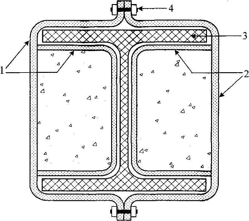
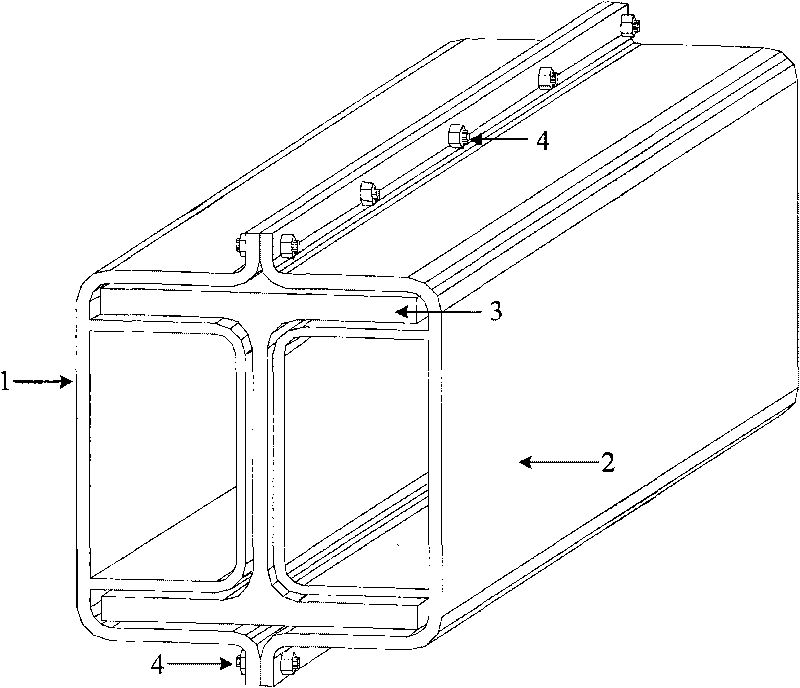
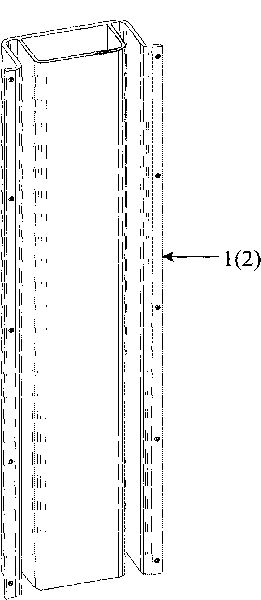
[0021] Such as figure 1 and figure 2 As shown, the anti-buckling energy-dissipating support consists of two "giant"-shaped fasteners 1-2 and a core hot-rolled H-shaped steel 3. The two "giant"-shaped fasteners 1-2 are respectively welded by a hat-shaped cold-formed thin-walled steel and a groove-shaped cold-formed thin-walled steel embedded in the hat-shaped cold-formed thin-walled steel; The zigzag fasteners 1 and 2 respectively have a closed rectangular tube, and concrete should be poured into the closed rectangular tube; the two "giant" zigzag fasteners 1 and 2 are connected together by bolts at the brim of the cap to form a peripheral restraint member. ""-shaped fasteners 1 to 2 form an H-shaped s...


PUM


Abstract

The invention discloses an E-shaped fastener constrained type assembled buckling-restrained energy-consumed brace, belonging to the technical field of structural engineering. The E-shaped fastener constrained type assembled buckling-restrained energy-consumed brace is characterized in that the brace comprises two E-shaped fasteners and a hot rolled H-shaped steel; the two E-shaped fasteners are connected together through bolts and form a periphery constrained component; enclosed rectangle tubes of the two E-shaped fasteners are internally injected with concretes; and appropriate gaps are left between the two E-shaped fasteners and the hot rolled H-shaped steel. The invention can provide lateral resistant effect to multiple-story and high-rise buildings and reach total cross-section buckling under the action of strong earthquake, thereby effectively consuming energy. By taking the hot rolled H-shaped steel as an inner core stressed component, cross sections have wide specification selection range, buckling loads with larger tonnage can be realized, and better ductility is achieved in comparison with the welding of I shaped steel. In addition, the invention has the advantages of easy material selecting, simple processing, convenient construction, low construction cost and convenience for industrial scale production.

Description

technical field [0001] The invention relates to a novel anti-buckling energy dissipation support, which belongs to the technical field of structural engineering. technical background [0002] After the Hanshin earthquake in Japan and the Northridge earthquake in the United States, buckling-resistant energy-dissipating braces, as an energy-dissipating and shock-absorbing component with superior performance, have been rapidly popularized and applied in Japan, the United States and other earthquake-prone developed countries. The anti-buckling energy-dissipating support consists of two parts: the inner core and the outer periphery: the inner core directly bears the axial load, and generally adopts steel with a low yield point. The reason why the steel with a low yield point is used is to prevent buckling under moderate and large earthquakes The energy-dissipating support can enter yield before the frame, thereby improving the ductility of the structure and giving full play to th...

Claims


Application Information

Patent Timeline
Patent Type & Authority Applications(China)
IPC IPC(8): E04B1/98E04B1/30
Inventor 郭彦林江磊鑫田广宇兰涛
Owner TSINGHUA UNIV
Why Eureka
Try Eureka