
Gamma ray imaging device

An imaging device and gamma-ray technology, which is applied in the field of gamma-ray radiation measurement, can solve the problems of difficult acquisition, high cost, and undisclosed specific size of the scintillation crystal of the collimator, and achieve the effect of improving linear correspondence and simple structure

Inactive Publication Date: 2010-06-02
CHINA INSTITUTE OF ATOMIC ENERGY
View PDF0 Cites 16 Cited by
  • Summary
  • Abstract
  • Description
  • Claims
  • Application Information

AI Technical Summary

Problems solved by technology

The first type of imaging device is limited to a small scanning range, and it is difficult to collect the "hot spots" distribution area map in a large space. The second type of imaging device generally depends on high-performance components (microchannel plate, fiber optic cone, semiconductor CCD, etc.), can be realized, and the cost is expensive
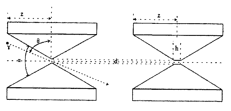
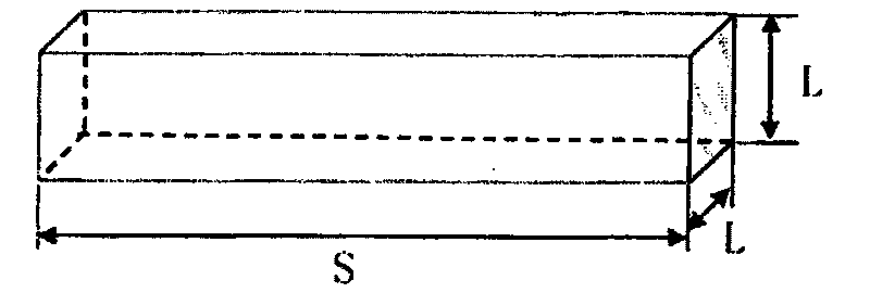
In addition, the specific dimensions of the collimator and the scintillation crystal of the above-mentioned imaging device have not been disclosed yet.

Method used


Image

  • Gamma ray imaging device
  • Gamma ray imaging device
  • Gamma ray imaging device

Examples


Embodiment 1

[0020] Such as figure 1 As shown, the gamma-ray imaging device provided by the present invention includes a gamma camera and a data acquisition and processing system, wherein the gamma camera includes a pinhole collimator 1, a scintillation crystal 2, a position-sensitive photomultiplier tube 3, and a resistance grid 4, The whole gamma camera is composed of three sections of threaded cylinders, the first section of cylinder is located at the front end of the gamma camera, and the pinhole collimator 1 is connected with the housing of the gamma camera by screws, so as to facilitate the replacement of different radiation sources when measuring different radiation sources. Pinhole collimator 1; the second cylinder is located in the middle of the gamma camera, and scintillation crystal 2, position-sensitive photomultiplier tube 3 and resistor grid 4 are installed in sequence; the third cylinder is located at the end of the gamma camera, as the gamma camera The back cover, and leads...


PUM

PropertyMeasurementUnit
Side lengthaaaaaaaaaa
Thicknessaaaaaaaaaa

Abstract

The invention belongs to the field of Gamma ray radiation measurement, particularly relates to a Gamma ray imaging device which comprises a Gamma camera and a data acquisition processing system, wherein the Gamma camera comprises a pinhole collimator, a scintillation crystal, a position sensitive photo-multiplier tube and resistor grids; and electrical signals output by the resistor grids are input to the data acquisition processing system arranged outside the Gamma camera. The Gamma ray imaging device produced according to the technical scheme of the invention can measure the large-scaled decommissioning site of nuclear facilities in real time to obtain a region distribution map of hot points, which includes nuclide positioning, nuclide identification and nuclide dosage.

Description

technical field [0001] The invention belongs to the field of gamma ray radiation measurement, in particular to a gamma ray imaging device. Background technique [0002] A large number of nuclear facilities or some of their buildings and equipment have strong radioactivity during their operation and service. Such as nuclear facilities, equipment or individual components such as reactor main circuit system, spent fuel storage pool, reprocessing process pipeline, glove box heat chamber, etc., will be activated by radioactivity or surface contamination during operation and service, and have extremely strong radioactivity . As a result, the radiation field at the decommissioning site of nuclear facilities is strong, and it is difficult for personnel to approach, which brings great difficulties to the quantitative measurement of the source item investigation site and the positioning and measurement of pollution "hot spots". In order to determine the radioactivity status of decom...

Claims


Application Information

Patent Timeline
IPC IPC(8): G01T1/202G01T1/169
Inventor 肖雪夫韩永超肖文慧刘瑞瑞袁观俊陈凌马吉增
Owner CHINA INSTITUTE OF ATOMIC ENERGY
Learn More