Method and device for non-contact type synchronous transmission of energy and signal

An energy signal and synchronous transmission technology, applied in the field of energy transmission and signal transmission, can solve the problems of complex system control process, interference, and insufficient system stability, and achieve the effect of high system reliability and low cost.

Active Publication Date: 2010-06-02
重庆前卫无线电能传输研究院有限公司
View PDF0 Cites 25 Cited by
  • Summary
  • Abstract
  • Description
  • Claims
  • Application Information

AI Technical Summary

Problems solved by technology

This method increases the cost and complexity of the main circuit of the system,
[0005] Disadvantages of the existing technology: the traditional non-contact power transmission system can only realize energy transmission, its function is single, there...

Method used


Image

  • Method and device for non-contact type synchronous transmission of energy and signal
  • Method and device for non-contact type synchronous transmission of energy and signal
  • Method and device for non-contact type synchronous transmission of energy and signal

Examples


Embodiment 1

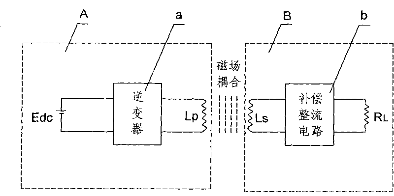
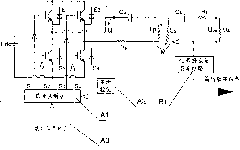
[0048] Embodiment 1: as figure 1 , as shown in 2, the device is composed of a primary circuit A and a secondary circuit B, wherein the primary circuit A is provided with a DC power supply Edc, an inverter a and an excitation coil Lp, the inverter a is mainly composed of a current detection unit A2, a signal The modulator A1, the first switch tube S1, the second switch tube S2, the third switch tube S3, the fourth switch tube S4 and a resonant network, the secondary circuit B is provided with a pickup coil Ls, a compensation rectification filter circuit b and Load resistor RL, the key of which is: the signal modulator A1 in the inverter a is also connected to a digital signal input unit A3, and the secondary circuit B is also provided with a signal extraction and recovery circuit B1, the signal extraction The input terminal of the recovery circuit B1 is connected to the secondary loop B, and the output terminal of the signal extraction and recovery circuit B1 outputs a digital ...

Embodiment 2

[0057] Embodiment 2: as Figure 7 As shown, the signal extraction and restoration circuit B1 is composed of a first envelope detector B1a, a power supply voltage circuit B1d and a voltage comparator B1c, wherein the first envelope detector B1a is mainly composed of a first diode D1, a first Composed of resistor R1 and first capacitor C1, the output terminal of the first envelope detector B1a is also composed of a third resistor R3 and the third capacitor C3 to form a low-pass filter, and the output terminal of the first envelope detector B1a outputs The voltage Vout1 is connected to the inverting input terminal of the voltage comparator B1c, the power supply voltage circuit B1d outputs a decision voltage Vout4 to the non-inverting input terminal of the voltage comparator B1c, and the output terminal of the voltage comparator B1c outputs The restored digital signal.

[0058] The working principle of the present invention:

[0059] When the system is working, the excitation co...


PUM


Abstract

The invention discloses a method for the non-contact type synchronous transmission of energy and signal. The method is characterized by comprising the following steps: establishing an AC electric energy transmission system of non-contact type; mounting a signal modulator in a primary loop; providing a digital signal for the signal modulator; extracting signal characteristics from a secondary loop and restoring the digital signal when the secondary loop receives electric energy; and finally realizing the non-contact type synchronous transmission of the energy and the signal. The non-contact type device for synchronously transmitting energy and signal, which is used for realizing the method, is provided with a DC power supply, an inverter and an exciting coil in the primary loop and characterized in that the signal modulator in the inverter is connected with a digital signal input unit and provided with a signal extracting and restoring circuit; and the output end of the signal extracting and restoring circuit outputs the restored digital signal. The invention has the advantages of easiness, practicability and low cost, restores the energy as a digital signal and has higher system reliability.

Description

technical field [0001] The invention belongs to the field of energy transmission and signal transmission, in particular to a non-contact energy signal synchronous transmission method and a device thereof. Background technique [0002] With the development of science and technology, non-contact energy transmission has been widely used in the fields of power transmission and automatic control, such as figure 1 The traditional non-contact power transmission system shown is composed of a primary loop and a secondary loop. The primary loop includes a DC power supply, an inverter, and an excitation coil. The secondary loop includes a pick-up coil, a compensation, rectification and filtering unit, and a load. The primary loop The inverter converts the direct current into a high-frequency alternating current, and then forms a high-frequency alternating magnetic field near the exciting coil, and the pick-up coil obtains energy from the magnetic field through electromagnetic induction...

Claims


Application Information

Patent Timeline
IPC IPC(8): H02M3/335H02M5/10
Inventor 孙跃唐春森戴欣王智慧苏玉刚
Owner 重庆前卫无线电能传输研究院有限公司
Why Eureka
Try Eureka