Flue gas mixing element and flue gas denitration system using flue gas mixing element

A technology of flue gas mixing and components, which is applied in the field of flue gas purification, can solve the problems of unsatisfactory dispersion effect and achieve a favorable mixing effect

Inactive Publication Date: 2010-06-09
CPI YUANDA ENVIRONMENTAL PROTECTION ENG
View PDF1 Cites 4 Cited by
  • Summary
  • Abstract
  • Description
  • Claims
  • Application Information

AI Technical Summary

Problems solved by technology

However, the dispersion effect of this mixing element is not ideal

Method used


Image

  • Flue gas mixing element and flue gas denitration system using flue gas mixing element
  • Flue gas mixing element and flue gas denitration system using flue gas mixing element

Examples


Embodiment Construction

[0014] Hereinafter, preferred embodiments of the present invention will be described in detail with reference to the accompanying drawings.

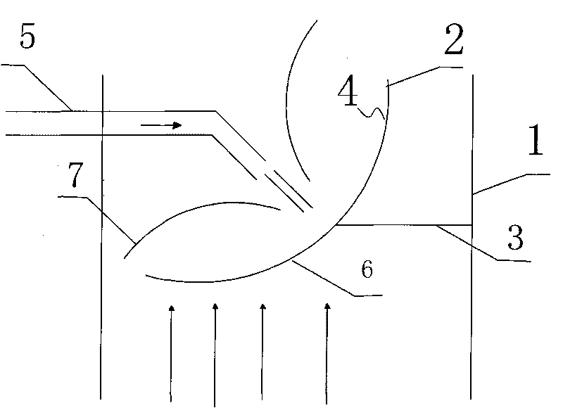
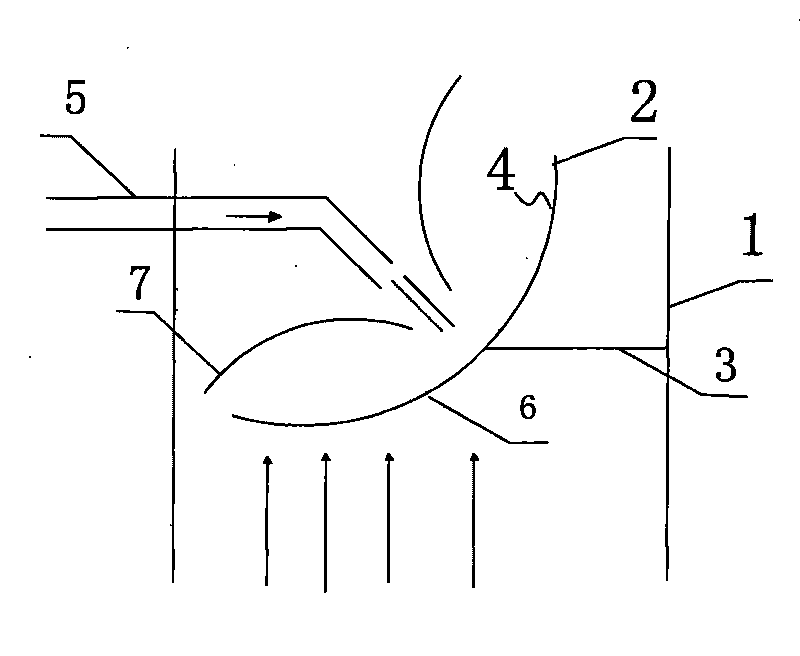
[0015] see figure 1 A mixing element 2 is set in the pipe 1 of the flue gas and reducing gas mixing part of the flue gas denitrification system, and the mixing element 2 is fixed on the inner wall of the pipe 1 through a support beam 3. The mixing element 2 is arc-shaped and placed obliquely In the pipeline 1, the backflow surface 4 of the mixing element 2 is concave and is opposite to the nozzle of the reducing agent nozzle 5, the backflow surface 4 of the mixing element 2 is not in contact with the nozzle of the reducing agent nozzle 5, and the flow direction of the mixing element 2 The surface 6 is convex and is opposite to the flow direction of the flue gas. In this way, when the reducing agent is sprayed onto the backflow surface 4 of the mixing element 2, it will evenly diffuse into a thin gas film 7; at the same time, when the fl...


PUM


Abstract

The invention provides a flue gas mixing element with better dispersion effect in a flue gas denitration system. The back flow surface of the mixing element is a concave surface. The invention also provides the flue gas denitration system using the flue gas mixing element. The mixing element is arranged in a pipeline of a flue gas and reducing gas mixing part of the flue gas denitration system; the mixing element is obliquely arranged in the pipeline; the back flow surface of the mixing element is the concave surface and is opposite to a spout of a reducing agent spray pipe; and the front flow surface of the mixing element is opposite to the flowing direction of the flue gas. Therefore, when a reducing agent is sprayed to the back flow surface of the mixing element, the reducing agent is evenly dispersed to form a layer of thin air film; and meanwhile, after the flue gas meets the mixing element, disturbance is formed so that the flue gas and the ammonia gas are mixed fully.

Description

technical field [0001] The invention relates to the technical field of flue gas purification, in particular to a flue gas mixing device in a flue gas denitrification system and a flue gas denitrification system. Background technique [0002] Nitrogen oxides, as one of the main air pollutants, have received more and more attention. Nitrogen oxides will become another key area of ​​national pollution control after desulfurization. SCR flue gas denitration technology is one of the most widely used flue gas denitrification technologies at present. It has the advantages of high denitrification efficiency, good selectivity, stable and reliable operation, etc. The key to SCR technology, one is the catalyst; the other is whether there is a uniform flow field distribution, that is, the NH in the flue gas 3 with NO x Uniformity. When ammonia is locally excessive, it will cause a high local ammonia escape rate, and the escaped ammonia will combine with SO 3 The reaction produces su...

Claims


Application Information

Patent Timeline
IPC IPC(8): B01D53/79B01D53/56
Inventor 杜云贵洪燕吴其荣魏丽斯蒙剑但康周涛
Owner CPI YUANDA ENVIRONMENTAL PROTECTION ENG
Why Eureka
Try Eureka