Dyeing machine for atomizing dyestuff

A dye atomization and dyeing machine technology, applied in the field of dyeing machines, can solve the problems of high production costs

Inactive Publication Date: 2010-06-09
石建明
View PDF0 Cites 5 Cited by
  • Summary
  • Abstract
  • Description
  • Claims
  • Application Information

AI Technical Summary

Problems solved by technology

Therefore, the production cost of this high temperature and high pressure liquid flow dyeing machine is higher

Method used


Image

  • Dyeing machine for atomizing dyestuff
  • Dyeing machine for atomizing dyestuff
  • Dyeing machine for atomizing dyestuff

Examples


Embodiment Construction

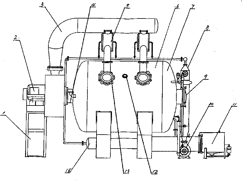
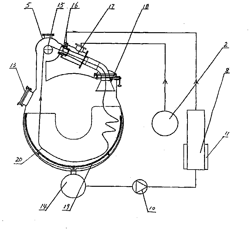
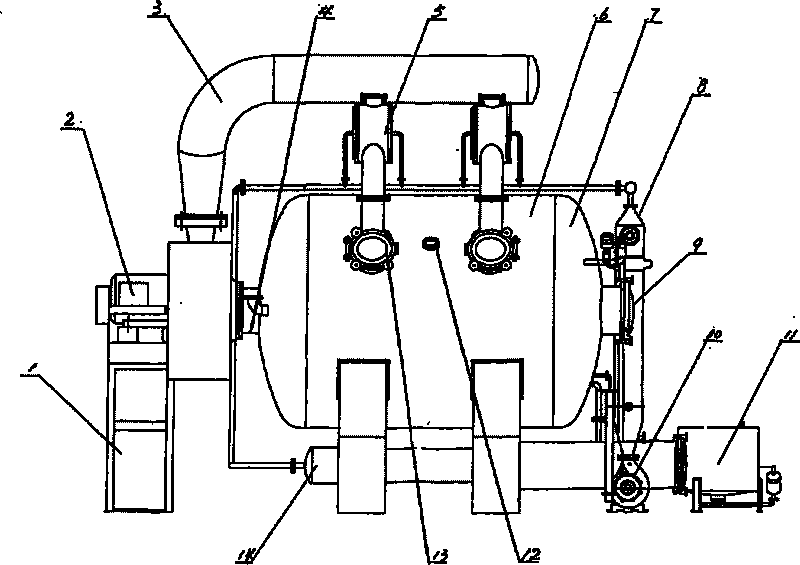
[0010] Such as figure 1 with figure 2 As shown, a dyeing machine of the present invention that atomizes dyes includes a cylinder 6 , a heat exchanger 8 , a fan 2 and a barrel 11 . Wherein, the simplified body 6 is a closed cylinder, which is arranged horizontally, and an operation hole 13 is processed on the upper wall of the cylinder, and a dyeing tank 19 is processed inside it. Dyeing tank 19 wherein is circumferentially arranged along the lower half of cylinder body 6 inwalls, and two openings are processed on the upper wall of simplified body 6 corresponding to the two ends of dyeing tank 19, and swing mechanism 18 is fixed in one of the openings. The effect of swing mechanism 18 is to prevent that dyed fabric 20 knots. A wheel housing 5 is arranged above the opening without the swing mechanism 18, and two ports are processed on the wheel shell 5, one of which communicates with the opening below it through a pipe, and the other port is connected to the simplified body w...


PUM


Abstract

The invention relates to a dyeing machine for atomizing dyestuff. The dyeing machine makes use of high-pressure airflow to atomize dye liquor for fabric dyeing, and comprises a cylinder body, a lift reel and a feed cylinder. The dyeing machine is characterized in that the cylinder body is horizontally arranged and the inside of the cylinder body is provided with a dye vat; the upper wall of the cylinder body corresponding to both ends of the dye vat is provided with two openings; the inside of one opening is provided with a cloth arrangement mechanism, and a wheel hull is arranged above the other opening; the wheel hull is communicated with the two openings below the wheel hull through pipes; the lift reel is positioned inside the wheel hull; the inside of a pipe between the wheel hull and the cloth arrangement mechanism is provided with a nozzle and a spray head; a heat exchanger, a feed pump and a fan are arranged outside the cylinder body; and a reflux mechanism is arranged under the cylinder body.

Description

[0001] The invention relates to a dyeing machine. Specifically, it is a dyeing machine that uses high-pressure airflow to atomize dyes for dyeing. Background technique [0002] Existing dyeing machine mainly is high temperature and high pressure liquid flow dyeing machine to fabric dyeing. This kind of dyeing machine adopts a longer length of more than 6 meters to increase the cycle length of the dyed cloth in the dyeing solution and improve the dyeing rate. When working, the dyed fabric circulates in the dyeing solution in the simplified body after bypassing the cloth lifting wheel and the nozzle. The circulation power of the fabric is mainly based on the high-pressure water flow from the nozzle, supplemented by the transmission of the fabric lifting wheel to the fabric. Since the dyeing liquid is both the dyeing medium and the main carrier of fabric movement, more water is needed. When the amount of water is too much, not only more heat energy is consumed for heating the ...

Claims


Application Information

Patent Timeline
Patent Type & Authority Applications(China)
IPC IPC(8): D06B1/02
Inventor 石建明
Owner 石建明
Why Eureka
Try Eureka