
Automatic control system for aligning and coupling optical fiber and electrooptical modulator

An electro-optical modulator and automatic control technology, which is applied in the program control of the sequence/logic controller, the coupling of the optical waveguide, the electrical program control, etc., can solve the problems of difficult alignment, long time consumption of optical fibers, and inability to accurately locate. To achieve the effect of solving time-consuming

Inactive Publication Date: 2010-06-09
INST OF SEMICONDUCTORS - CHINESE ACAD OF SCI
View PDF0 Cites 14 Cited by
  • Summary
  • Abstract
  • Description
  • Claims
  • Application Information

AI Technical Summary

Problems solved by technology

[0009] In view of this, the main purpose of the present invention is to solve the problems of traditional manual adjustment of optical fiber, such as time-consuming, difficult alignment, easy disturbance from the outside, and inability to accurately locate, etc., to provide an automatic control system for the alignment coupling of optical fiber and electro-optical modulator

Method used


Image

  • Automatic control system for aligning and coupling optical fiber and electrooptical modulator
  • Automatic control system for aligning and coupling optical fiber and electrooptical modulator
  • Automatic control system for aligning and coupling optical fiber and electrooptical modulator

Examples


Embodiment Construction

[0039] In order to make the object, technical solution and advantages of the present invention clearer, the present invention will be described in further detail below in conjunction with specific embodiments and with reference to the accompanying drawings.

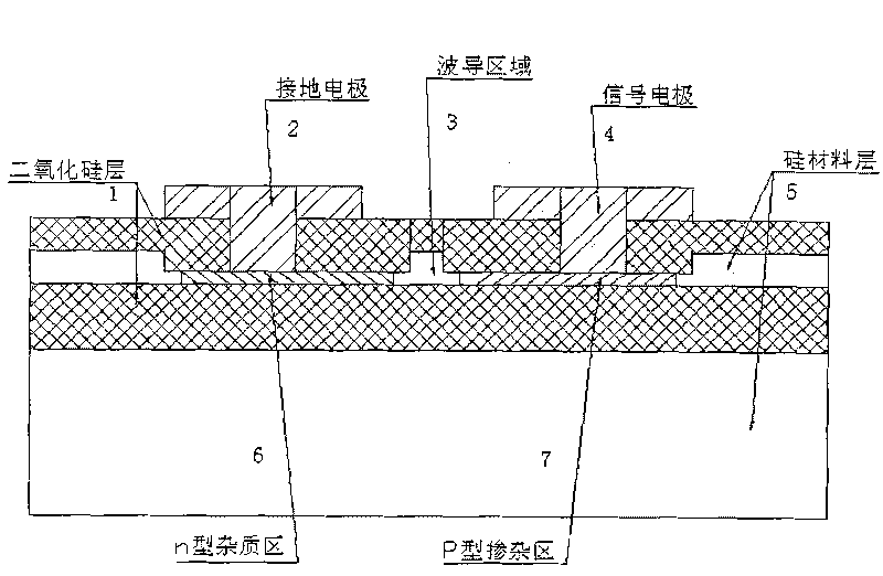
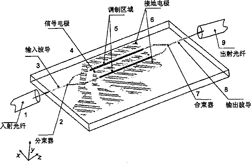
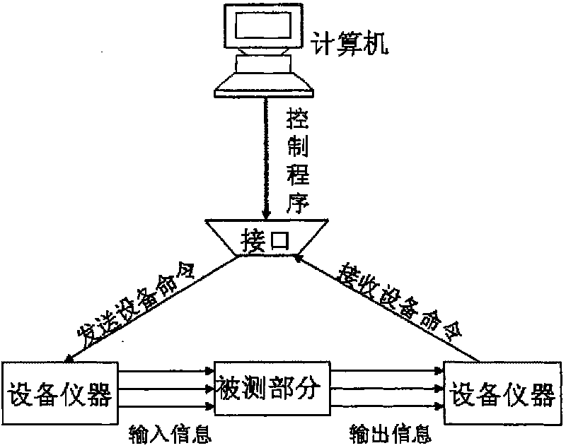
[0040] Such as Figure 4 as shown, Figure 4It is a structural schematic diagram of an automatic control system for aligning and coupling an optical fiber and an electro-optical modulator provided by the present invention. Interface bus (GPIB) card, GPIB cable, serial port communication cable and computer, the tunable laser is connected with the input fiber, the optical power meter is connected with the output fiber respectively, and the electro-optic modulator is placed between the input fiber and the Between the output fibers, the input fiber and the output fiber are fixed on the adjustment frame, the adjustment frame is connected to the stepper motor controller, the stepper motor controller is connected to the GPIB ca...


PUM


Abstract

The invention discloses an automatic control system for aligning and coupling an optical fiber and an electrooptical modulator. The system comprises a tunable laser, an optical power meter, the electrooptical modulator, a polarization-preserving optical fiber, a regulating frame, a step motor controller, a general-purpose interface bus (GPIB) card, a GPIB cable, a serial port communication cable and a computer. The tunable laser is connected with input optical fibers, the optical power meter is respectively connected with the output optical fibers, the electrooptical modulator is arranged among the input optical fibers and the output optical fibers, the input optical fibers and the output optical fibers are fixed on the regulating frame which is connected with the step motor controller, the step motor controller is connected with the GPIB card in the computer through the GPIB cable, and the optical power meter is connected with the computer through the serial port communication cable. The invention solves the problems that the traditional manual regulation of optical fibers has long time and the optical fibers are not aligned easily and cannot be precisely positioned due to the disturbance from external environments.

Description

technical field [0001] The invention relates to the technical field of optical fiber communication and electro-optic modulator, in particular to an automatic control system for aligning and coupling optical fiber and electro-optic modulator. Background technique [0002] The Dense Wavelength Division Multiplexing (DWDM) system has the remarkable characteristics of large transmission capacity and flexible networking, and has become the mainstream technology of long-distance optical fiber communication. As one of the key points of the DWDM system, the electro-optic modulator is used to modulate the continuous light wave (carrier) into an optical signal carrying specific information. Electro-optic modulators can be divided into electro-optic modulators, thermo-optic modulators, acousto-optic modulators, and all-optical modulators according to their modulation principles. The principle of the electro-optic modulator is to change the refractive index of the material under the in...

Claims


Application Information

Patent Timeline
IPC IPC(8): G02B6/42G02F1/025G05B19/04G05D3/12
Inventor 徐海华徐学俊陈少武余金中
Owner INST OF SEMICONDUCTORS - CHINESE ACAD OF SCI
Learn More