Adjustable-speed magnetic induction coupler

A magnetic induction and coupling technology, applied in electrical components, electromechanical devices, electromechanical transmission devices, etc., can solve problems such as reduced efficiency, increased rotor loss, and inconspicuousness, so as to improve the transmitted torque and avoid vibration interference. , to achieve the effect of adjustable speed

Inactive Publication Date: 2010-06-09
常州市长江热能有限公司
View PDF1 Cites 33 Cited by
  • Summary
  • Abstract
  • Description
  • Claims
  • Application Information

AI Technical Summary

Problems solved by technology

However, the above-mentioned permanent magnet eddy current transmission device does not design a detailed air gap adjustment device, nor does it have the principle of air gap adjustment; the above-mentioned device grooves on the surface of the copper plate and embeds steel sheets, although it can achieve a certain magnetic concentration effect, But it is not obvious, and the skin effect of deep grooves cannot be produced, and the transmission performance is restricted
When the operating speed of the above-mentioned device changes sharply, if the speed becomes small, the excessive slip will cause the rotor loss to increase sharply, the efficiency will decrease, and the heat will be serious.

Method used


Image

  • Adjustable-speed magnetic induction coupler
  • Adjustable-speed magnetic induction coupler
  • Adjustable-speed magnetic induction coupler

Examples


Embodiment Construction

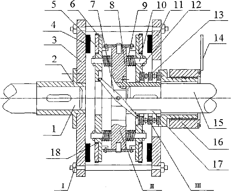
[0027] The overall structure of the present invention is as figure 1 As shown, the device is mainly composed of a driving disc assembly (I), a driven disc assembly (II) and a speed regulating device assembly (III). The driving disc assembly (I) is connected with the driving shaft through a flat key; the driven disc assembly (II) is installed at one end of the driven shaft; the speed regulating device assembly (III) is connected with the driven disc assembly (II).

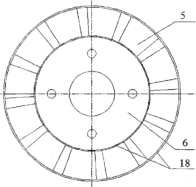
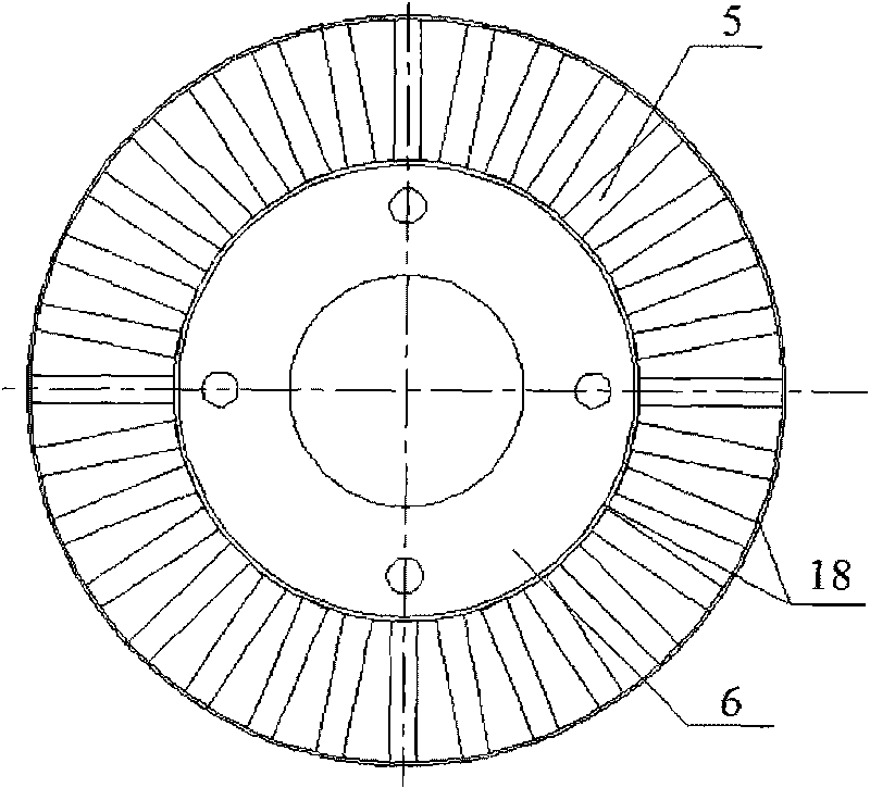
[0028] Concrete structure of the present invention: drive disc assembly (I) such as figure 1 As shown, it includes a sleeve 1 (2), two drive disc substrates 3, 11 and permanent magnets 4; the permanent magnets 4 are closely arranged and bonded on the end faces of the substrates 3, 11 according to the even-numbered N pole and S pole. The S pole can be a single pole, or multiple ring magnets with the same polarity and size, and the two drive disc bases are connected by screws; the driven disc assembly (II) includes t...


PUM


Abstract

The invention discloses an adjustable-speed magnetic induction coupler, which relates to the technical field of transmission in mechanical engineering, and comprises a driving disk assembly (I) and a driven disk assembly (II), wherein the driven disk assembly (II) comprises a driven disk substrate 1, a driven disk substrate 2, a driven disk substrate 3, sectorial copper plates or rectangular copper bars, a rotary connecting rod, springs, sliding rods and a sleeve 2; the driven disk substrate material is steel disk, the end faces of the driven disk substrates1 and 3 are provided with deep slots of which the depth is greater than half the thickness of the substrates, and the sectorial copper plates or rectangular copper bars, which have the same shape as permanent magnets, are rotationally embedded in the slots; the sliding rods are distributed on the two end faces of the driven disk substrate 2 along a circumferential direction, the springs are sleeved in the sliding rods, and the driven disk substrates 1 and 3 are fixed on the sliding rods and can compress the springs along the sliding rods; and the rotary connecting rods are connected with the driven disk substrates 1 and 3 and are fixed on the driven disk substrate 2 rotationally. The adjustable-speed magnetic induction coupler can be used in power transmission mechanisms between loads and high- vibration motors such as coal mills, crushers and coal belt conveyers and used in transmission systems of other devices.

Description

technical field [0001] The invention relates to the technical field of transmission in mechanical engineering, in particular to a non-contact magnetic induction coupling. It can be used in the power transmission mechanism between the motor and the load of the coal mill, the crusher, the coal conveying belt conveyor, the compressor, etc., and the transmission system of other devices. Background technique [0002] In the field of mechanical engineering, the coupling is an important part of the mechanical transmission system. It is called one of the three major devices in the mechanical transmission. It is widely used in various fields of the machinery industry and is widely used in mines, Metallurgy, aviation, weapons, hydropower, chemical industry, textile and transportation sectors. However, since the coupling is a rigid connection and mechanical force transmits torque, the axial offset during installation will generate restoring forces and moments, which increase the load ...

Claims


Application Information

Patent Timeline
Patent Type & Authority Applications(China)
IPC IPC(8): H02K51/00
Inventor 杨超君郑武李直腾蒋生发
Owner 常州市长江热能有限公司
Why Eureka
Try Eureka