AC/DC convertor

A converter and circuit technology, applied in the direction of conversion equipment with intermediate conversion to AC, irreversible conversion of AC power input into DC power output, sustainable manufacturing/processing, etc., can solve the problem that the output diode is difficult to achieve zero current shutdown , large conduction loss, large rectifier bridge loss, etc., to achieve the effect of improving conversion efficiency and power supply efficiency, reducing conduction loss, and reducing switching loss

Inactive Publication Date: 2010-06-09
EMERSON NETWORK POWER CO LTD
View PDF0 Cites 40 Cited by
  • Summary
  • Abstract
  • Description
  • Claims
  • Application Information

AI Technical Summary

Problems solved by technology

Since the input current of the PFC flows through the rectifier bridge D1~D4, the loss on the rectifier bridge is large, and it is difficult to improve the power supply efficiency; while the DC / DC adopts a phase-shifted full-bridge topology, the lagging bridge arm is not easy to achieve ZVS, and the output diode D6 and D7 are also difficult to achieve zero-current shutdown, and the conduction loss on them is also relatively large. In addition, due to the large volume of the output inductor Lo, it is difficult to increase the power density of the power supply

Method used


Image

  • AC/DC convertor
  • AC/DC convertor
  • AC/DC convertor

Examples


specific Embodiment approach 1

[0045] Specific implementation mode 1: half-bridge three-level PFC with mid-point clamp and LLC series resonant half-bridge mid-point clamp DC / DC converter with output synchronous rectification

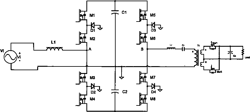
[0046] like figure 2The DC bus voltage of the shown PFC converter is greater than twice the peak value of the input Vi, and Vi is the input power of the PFC circuit. The AC / DC converter includes the input filter inductor L1 of PFC, the power switch tubes M1, M2, M3, M4 of the half-bridge three-level PFC with neutral point clamping, the neutral point clamping diodes D1, D2, and the DC bus Capacitors C1, C2. The midpoint of the DC bus capacitors C1 and C2 is the clamp midpoint.

[0047] The DC / DC converter includes power conversion switch tubes M5, M6, M7, M8, midpoint clamping diodes D3, D4, resonant inductance Lr of LLC series resonance, resonant capacitor Cr of LLC series resonance, and output isolation transformer T1. The excitation inductance of the output isolation transformer...

specific Embodiment approach 2

[0059] Specific implementation mode 2: half-bridge three-level PFC with mid-point clamp and LLC series resonant half-bridge mid-point clamp DC / DC converter with output synchronous rectification

[0060] like Figure 8 The converter shown is the same as the basic circuit of Embodiment 1, the difference is that the resonant circuit is composed of separate inductors Lm, Lr, and Cr, instead of using the excitation inductance of the output isolation transformer for resonance.

specific Embodiment approach 3

[0061] Specific implementation mode three: full bridge PFC with neutral point clamp and LLC series resonant full bridge neutral point clamped DC / DC converter with output synchronous rectification

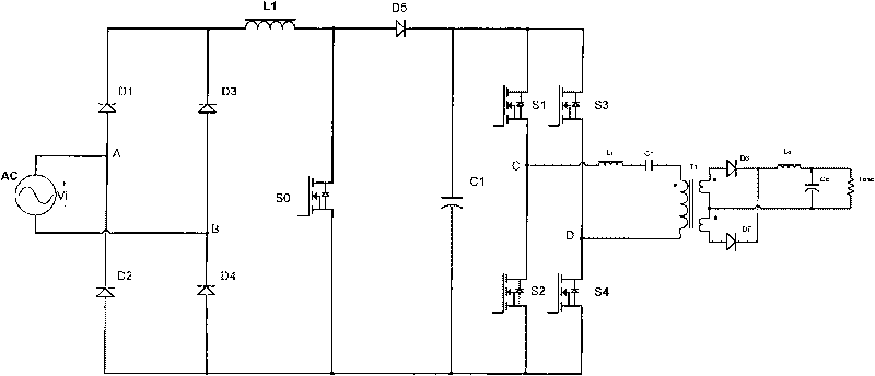
[0062] like Figure 9 The converter shown is the same as the basic circuit of the specific embodiment 1. One of the differences is: the PFC is a mid-point clamped full-bridge multi-level PFC, not a half-bridge three-level PFC with a mid-point clamp; the difference The second is: the DC / DC converter is an LLC series resonant full-bridge mid-point clamp DC / DC converter with output synchronous rectification, not an LLC series resonant half-bridge mid-point clamp DC / DC converter with output synchronous rectification device. The third difference is: the input filter inductor of PFC is replaced by two separate input filter inductors L2 and L3, which are respectively connected to both ends of the input power supply Vi. The inductance of the input filter inductor L1 at one end.

[0063] ...


PUM


Abstract

The invention discloses an AC / DC convertor, which comprises a forestage PFC circuit and a post-stage DC / DC convertor, and is characterized in that: the PFC circuit is a natural-point-clamped PFC circuit; and the DC / DC convertor is an LLC convertor with synchronous rectification. The AC / DC convertor has the AC / DC function, realizes the input PFC function, and ensures that the input current follows input voltage and an output communication power supply loads the required 48V voltage, 12V voltage or voltage in other power grades. The voltage stress of a power switching tube of the natural-point-clamped circuit is half of that of a power switching tube of a common two-level PFC, so the model selection is easy; the voltage at two ends of an input filter inductor is multi-level, and zero crossing points of inductive current are multiple, so the size of the inductor can be reduced, and the power density of the power supply can be improved. The power switching tube of the DC / DC convertor works in a ZCS or ZVS state, so the switching loss thereof can be reduced. An input synchronous rectifying field effect transistor is adopted to replace an output rectifying diode, so the conduction loss of the output rectifying diode can be reduced, and the conversion efficiency of the DC / DC convertor is further improved.

Description

technical field [0001] The invention relates to a rectifying power supply, in particular to an AC / DC converter. Background technique [0002] In the rectification process from AC to DC (AC / DC), not only the voltage conversion function needs to be realized, but also the power factor (Power Factor, referred to as PF) and total harmonic content (Total Harmonics Distortion, referred to as THD) need to be met by various power standards. ) and electromagnetic interference (Electromagnetic Inference, referred to as EMI) requirements. The existing AC / DC converter includes a power factor correction (Power Factor Correction, PFC circuit for short) of the preceding stage and a DC / DC converter of the subsequent stage, and the output end of the PFC is connected to the input end of the DC / DC converter. figure 1 The commonly used AC / DC converter topology is shown. AC is the AC input power supply. The PFC circuit includes a rectifier bridge composed of diodes D1~D4, BOOST rectifier inducto...

Claims


Application Information

Patent Timeline
Patent Type & Authority Applications(China)
IPC IPC(8): H02M7/02H02M3/28
CPCY02P80/10
Inventor 弗兰克·赫尔特胡永辉武志贤吴云黄庆义黄立巍
Owner EMERSON NETWORK POWER CO LTD
Why Eureka
Try Eureka