Silicon controlled drive circuit, device and control method thereof

A technology of driving circuit and driving method, which is applied in the circuit field, can solve the problems of poor load capacity and high cost, and achieve the effects of strong load capacity, low cost and energy saving

Inactive Publication Date: 2010-06-09
SHENZHEN H&T INTELLIGENT CONTROL
View PDF0 Cites 3 Cited by
  • Summary
  • Abstract
  • Description
  • Claims
  • Application Information

AI Technical Summary

Problems solved by technology

[0003] The technical problem to be solved by the present invention is to provide a thyristor driving circuit, device and control meth

Method used


Image

  • Silicon controlled drive circuit, device and control method thereof
  • Silicon controlled drive circuit, device and control method thereof
  • Silicon controlled drive circuit, device and control method thereof

Examples


Example Embodiment

[0022] Embodiments of the present invention will be further described below in conjunction with the accompanying drawings.

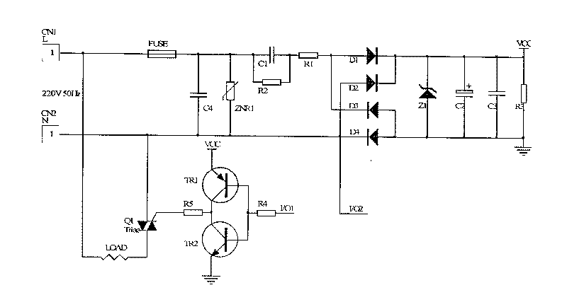
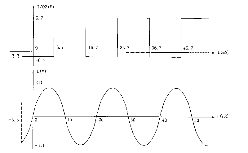
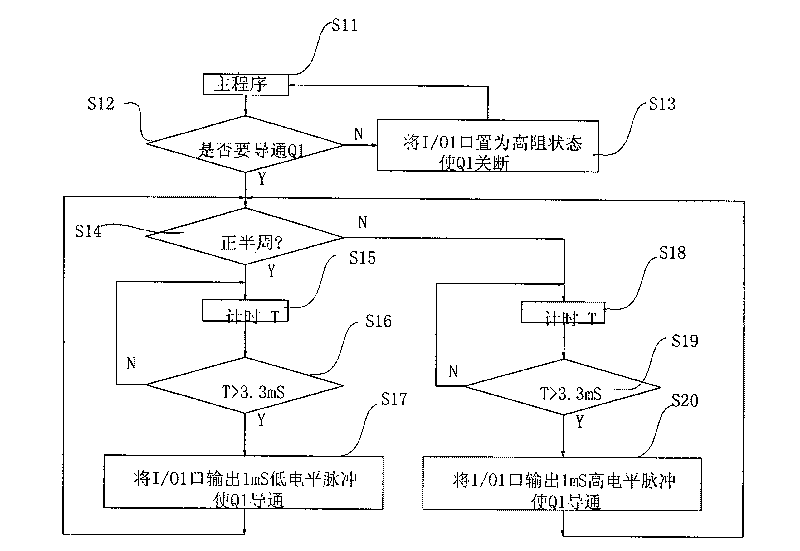
[0023] like figure 1 As shown, in the first embodiment of the present invention, the thyristor drive circuit includes a drive unit, a thyristor controlled by the drive unit, a control unit that provides a drive signal for the drive unit, and a control unit for the control The unit provides a DC power supply for power. The DC power supply is a DC power supply that obtains a DC voltage by full-wave rectification after AC power is stepped down by resistance and capacitance. The AC zero-crossing detection terminal of the control unit is directly connected to the full-wave rectifier. An AC input. The resistance-capacitance step-down element of the DC power supply is connected in series with the AC phase line, which is located before the input end of the full-wave rectified AC phase line. The AC zero-crossing detection terminal of the control unit is connect...


PUM


Abstract

The invention relates to a silicon controlled drive circuit, which comprises a drive unit, a silicon controlled thyristor which is controlled by the drive unit, a control unit for providing a drive signal for the drive unit, and a DC power supply for providing power for the control unit. The DC power supply is obtained in a mode that an alternating current is subjected to resistance-capacitance voltage reduction and full-wave rectification to acquire a DC voltage. A pin of the control unit is directly connected to an alternating current input end of a full-wave rectifier for acquiring a zero-crossing detection signal of the alternating current. The invention also relates to a silicon controlled drive device and a drive method. The silicon controlled drive circuit, the silicon controlled drive device and the control method thereof have the following advantages that: under the condition of the power supply subjected to resistance-capacitance voltage reduction, due to the adoption of the full-wave rectification, the silicon controlled drive circuit and the silicon controlled drive device have stronger load capacity due to the adoption of the resistance-capacitance voltage reduction with the same parameters, the parameters of resistance-capacitance voltage reducing device can be reduced, and the energy is saved; at the same time, as the zero-crossing detection circuit is simpler, the silicon controlled drive circuit and the silicon controlled drive device have lower cost.

Description

technical field [0001] The invention relates to the field of circuits, and more specifically relates to a thyristor drive circuit and a control method thereof. Background technique [0002] In the existing industrial fields that are applied to thyristors, especially in the field of small household appliances, due to the limitation of cost and volume, resistance-capacitance step-down power supplies are usually used. However, when using a resistance-capacitance step-down power supply circuit, in order to realize the driving of the thyristor, a half-bridge rectification type resistance-capacity step-down power supply circuit is usually used (because the drive of the thyristor generally needs to connect the power line L and VCC together , a half-bridge circuit can achieve this). The disadvantage of this circuit is: after the 220V AC mains is stepped down by capacitors and resistors, for the power supply required to support the entire control system, the AC mains is only valid f...

Claims


Application Information

Patent Timeline
IPC IPC(8): H03K17/73
CPCH02M2001/0006H02M5/2573H02M1/0006
Inventor 姜西辉刘建伟首召兵
Owner SHENZHEN H&T INTELLIGENT CONTROL
Why Eureka
Try Eureka