Method for automatically controlling received power in FSO system

A technology of received power and optical power, applied in transmission systems, electromagnetic wave transmission systems, free space transmission, etc., can solve the problems of large changes in the received optical power at the receiving end, unstable atmospheric space attenuation, and difficulty in ensuring optical power, etc. Achieve the effect of reducing the optical power range, enhancing the stability and reliability, and achieving good immediacy

Inactive Publication Date: 2010-06-09
NANJING UNIV
View PDF0 Cites 12 Cited by
  • Summary
  • Abstract
  • Description
  • Claims
  • Application Information

AI Technical Summary

Problems solved by technology

Although the optical receiver can have a dynamic range of about 20dB, it is difficult to ensure that the optical power is not overloaded
However, after encoding at the detector end, encoding judgment errors occur in a large range of optical power variation: when the received optical power value is large, the amplitude of the converted electrical pulse may not change due to the influence of the detector saturation effect, and it is

Method used


Image

  • Method for automatically controlling received power in FSO system
  • Method for automatically controlling received power in FSO system
  • Method for automatically controlling received power in FSO system

Examples


Embodiment Construction

[0029] The design making step that the present invention adopts is:

[0030] 1. Determine the position of the diaphragm and the size of the adjustable aperture according to the overall design requirements of the system. The design parameters involved are the aperture and focal length of the receiving optical antenna, the receiving aperture of the optical power detector (typical PIN and APD are 100-300um at the rate of 155M to 2.5G), the sensitivity of the optical power detector (-30~-50dBm ) and dynamic range (20 ~ 30dBm).

[0031] 2. The aperture is located between the receiving optical antenna and the optical power detector. It adopts a rectangular plate structure and is separated into two parallel upper and lower ends. For example, one end is fixed on the upper part, and the other end is controlled by a stepping motor to move up or down at the lower part. .

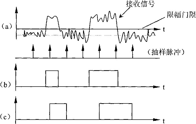
[0032] 3. The optical power sampling adopts the pulse timing sampling method, and the sampling period is set accor...


PUM


Abstract

The invention discloses a method for automatically controlling received power in an FSO system. In a receiving device of a detector of a free-space optics communication system, the received light power is controlled by a method of automatically extending to control a received angular aperture; the control of the received angular aperture is realized by an aperture adjustable diaphragm; a light power sampling system samples the detector regularly, and sample values are input to a microprocessor, compared with a received light power range value stored in the microprocessor, and processed; when the received light power range value is smaller than a fixed value, the aperture of the diaphragm is increased, and when the received light power range value is greater than the fixed value, the aperture of the diaphragm is decreased; and a processing result is used to control a stepping motor to move the position of one end of the diaphragm so as to change the clear aperture of the diaphragm and control the received light power range. By adjusting the detection light intensity, the light power change range of the receiving end is reduced effectively and the stability and reliability of the system are further strengthened.

Description

1. Technical field [0001] The invention is a design for controlling the receiving optical power by adopting the method of automatically stretching and controlling the receiving aperture angle, and is suitable for the free space optical communication system (FSO). 2. Background technology [0002] Optical fiber communication and wireless communication are currently hot technologies, and free space optical communication system is the product of the combination of the two. [0003] A typical FSO system (such as figure 1 (shown) is mainly composed of optical receiving and transmitting antennas and terminal equipment, and corresponding relay equipment is added for long-distance transmission. After the laser at the sending terminal is modulated by the signal current, it emits laser light with a signal. After being transmitted through the atmospheric channel, it reaches the receiving terminal. After the optical signal is processed by the photoelectric detector, it is restored to ...

Claims


Application Information

Patent Timeline
IPC IPC(8): H04B10/10H04B10/11
Inventor 许国良丁涛
Owner NANJING UNIV
Why Eureka
Try Eureka