Convection heat-radiation system for temperature control of electronic equipment close to space vehicle

It is a technology of electronic equipment and adjacent space, which is applied in the direction of electrical equipment construction parts, circuits, electrical components, etc. It can solve the problems of different equipment heat dissipation problems, different heat dissipation measures of stratospheric aircraft, etc., and achieve system reliability guarantee and structure Compactness, weight reduction effect

Inactive Publication Date: 2010-06-09
NANJING UNIV OF SCI & TECH
View PDF0 Cites 16 Cited by
  • Summary
  • Abstract
  • Description
  • Claims
  • Application Information

AI Technical Summary

Problems solved by technology

With the development of airship technology, the application of high-power electronic equipment in stratospheric airships is becoming more and more extensive. In order to ensure the normal operation of electronic equipment, corresponding heat dissipation measures must be taken. However, due to the unique environment of temperature and pressure in the Therefore, the cooling measures of stratospheric aircraft are not only different from ground equipment, but also different from flying objects such as satellites outside the atmosphere. Limits the application of high-power electronic equipment on th

Method used


Image

  • Convection heat-radiation system for temperature control of electronic equipment close to space vehicle
  • Convection heat-radiation system for temperature control of electronic equipment close to space vehicle
  • Convection heat-radiation system for temperature control of electronic equipment close to space vehicle

Examples


Embodiment Construction

[0009] The present invention will be described in further detail below in conjunction with the accompanying drawings.

[0010] Taking the realization of the temperature control requirement of electronic equipment at 35±5°C as an example, the specific implementation steps for realizing the present invention are as follows:

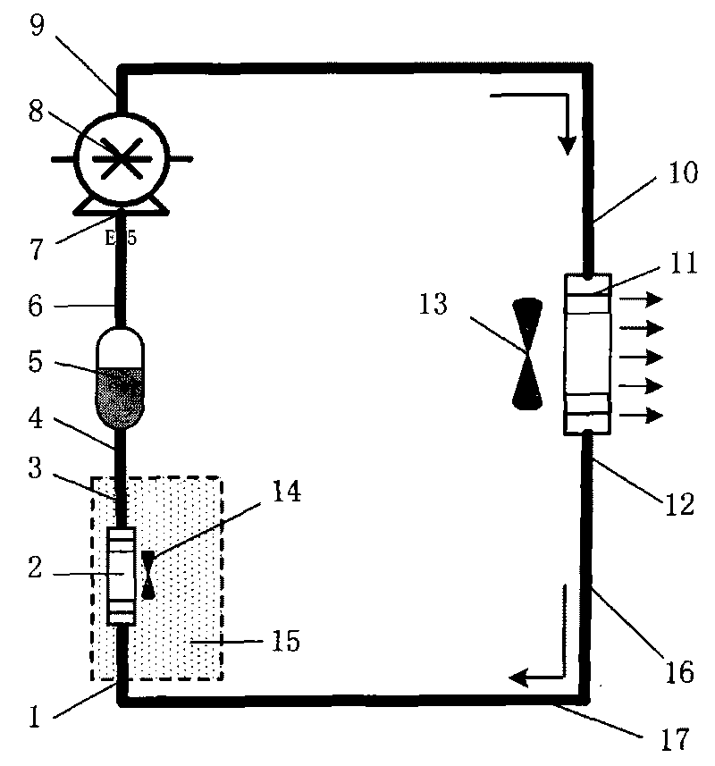
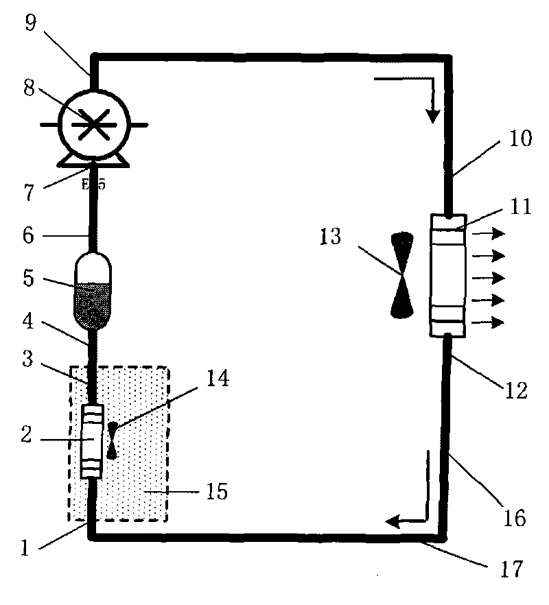
[0011] combine figure 1 , the electronic equipment cooling system of the present invention consists of an electronic equipment pressure holding cabin 15, a liquid storage tank 5, a pump 8, a tube-fin heat exchanger 2 in the cabin, a fan 14 for the radiator in the cabin, and a tube-fin heat exchanger 11 outside the cabin. , the outboard radiator is made up of blower fan 13, pipeline 16, and circulating fluid working medium 17.

[0012] 1. Design the fluid pump circuit to transfer the waste heat in the electronic equipment compartment to the external radiator, such as figure 1 As shown, the single-phase fluid circuit fluid working medium 17 is ethylene glyc...


PUM


Abstract

The invention discloses a convection heat-radiation system for temperature control of electronic equipment close to space vehicle, comprising an electronic equipment pressure maintaining cabin, a liquid storage tank, a pump, an in-cabin finned-pipe heat exchanger, a fan for an in-cabin radiator, an extravehicular finned-pipe heat exchanger, a fan for an extravehicular radiator, a pipeline and circulating fluid, the inlet of the pump is connected with the outlet of the liquid storage tank, the inlet of the liquid storage tank is connected with the outlet of the in-cabin finned-pipe heat exchanger, the inlet of the in-cabin finned-pipe heat exchanger is connected with the outlet of the extravehicular finned-pipe heat exchanger, the inlet of the extravehicular finned-pipe heat exchanger is connected with the outlet of the pump, and the circulating fluid working medium is filled in the pipeline; in the invention, a fluid loop coupling type convection radiator is arranged, waste heat in the electronic equipment is transmitted to the finned-pipe heat exchanger through the fluid loop and is discharged to the ambient atmosphere through the convection radiator driven by the motor; the convection radiator is used in special working environment at bottom part of a stratosphere to carry out heat radiation of high-power electronic equipment, and the structure is compact.

Description

technical field [0001] The invention relates to a heat dissipation system, in particular to a convection heat dissipation system used for temperature control of electronic equipment of an adjacent space vehicle. Background technique [0002] With the rapid development of science and technology and the continuous evolution of the concept of future information-based operations, the strategic value of "near space" (20-100 km altitude), an airspace that humans have seldom set foot in in the past, has gradually attracted attention. At the same time, Due to its advantages such as strong comprehensive capabilities and relatively low cost, near-space vehicles have become a hot spot for research and development by various countries. In addition, a number of flying objects for civil and commercial purposes are also emerging. With the development of airship technology, the application of high-power electronic equipment in stratospheric airships is becoming more and more extensive. In o...

Claims


Application Information

Patent Timeline
IPC IPC(8): H05K7/20H01L23/42
CPCH05K7/202
Inventor 宣益民韩玉阁李强马伟
Owner NANJING UNIV OF SCI & TECH
Why Eureka
Try Eureka