Heat-radiating device of electric component

A technology for electronic components and heat sinks, applied in the field of heat sinks for electronic components, can solve the problems that semiconductor LED lighting sources cannot be widely used, the service life of chips is reduced, and the heat sinks are bulky, etc. The effect of reducing impedance and improving heat dissipation

Inactive Publication Date: 2011-09-28
邢台绿时代光电科技有限公司
View PDF0 Cites 0 Cited by
  • Summary
  • Abstract
  • Description
  • Claims
  • Application Information

AI Technical Summary

Problems solved by technology

However, the fatal shortcoming of the semiconductor LED lighting source is that as the power increases, the heat generated by the chip increases rapidly, and the service life of the chip at high temperatures is greatly reduced. Experiments show that the service life of the semiconductor LED lighting source can be reduced below 30°C It can reach 100,000 hours, and below 90, the service life of semiconductor LED lighting sources can reach 5,000 hours, which is also the main reason why semiconductor LED lighting sources cannot be popularized and applied at present.
Moreover, for street lamps or household lighting LED lamps, the cooling device is heavy, which not only wastes aluminum material, increases its cost price, but also causes safety hazards, so it is difficult to promote

Method used


Image

  • Heat-radiating device of electric component
  • Heat-radiating device of electric component
  • Heat-radiating device of electric component

Examples


Embodiment Construction

[0014] The structure and operating principle of the heat sink for electronic components of the present invention will be further described in detail below in conjunction with the accompanying drawings.

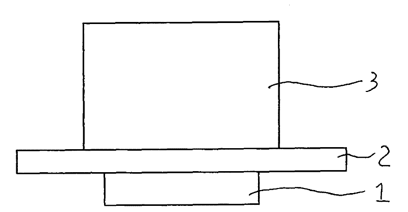
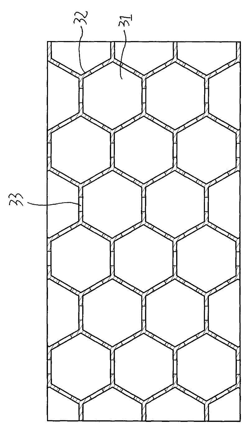
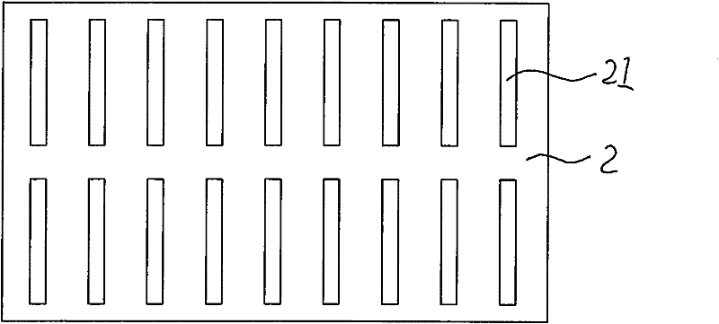
[0015] Such as figure 1 and figure 2 As shown, the heat dissipation device for electronic components of the present invention includes a heat dissipation substrate 2 and a heat dissipation fin 3. The heat dissipation substrate 2 and the electronic components 1 are tightly bonded together through a heat-conducting adhesive. The channel 31 and the heat dissipation wall 32 surrounding the heat dissipation channel 31 are composed. The cross section of the heat dissipation channel 31 is a regular hexagon, and the cross section of the heat sink 3 is honeycomb. The heat dissipation channel 31 forms air convection, and the heat dissipation method is mainly changed from radiation to convection. Mainly, supplemented by radiation, the thermal impedance of the heat dissipation channel i...


PUM


Abstract

The present invention belongs to the technical field of heat-radiating devices, in particular to a heat-radiating device of an electric component. The heat-radiating device is mainly characterized by comprising a heat-radiating substrate and a heat-radiating plate which are closely contacted with the electric component, wherein the heat-radiating plate comprises a plurality of heat-radiating channels which are vertical to the heat-radiating substrate and heat-radiating walls encircling to form the heat-radiating channel; the section of each heat-radiating channel is in a shape of regular hexagon; the section of the heat-radiating plate is a shape of honeycomb; and the heat-radiating walls are aluminum foil boards and a plurality of air holes are arranged on the aluminum foil boards vertically arranged on the heat-radiating channels; a plurality of gas channels interlinked with the heat-radiating channels are arranged on the heat-radiating substrate. The heat-radiating mode is changed from giving the priority to the radiation into giving the priority to convection assisted by the radiation, thus the thermal impedance of the heat-radiating channel is greatly reduced and air convection is more unobstructed; in addition, the heat-radiating plate the section of which is in a shape of honeycomb ensures that the heat-radiating area reaches the maximum. The heat-radiating device of an electric component provided by the present invention solves the problem that the service life of the traditional electronic component is short caused by ineffective temperature reduction.

Description

technical field [0001] The invention belongs to the technical field of heat dissipation devices, in particular to a heat dissipation device for electronic components. Background technique [0002] The application of electronic components is becoming more and more widespread, but the heat dissipation of electronic components has always plagued the development of technology. At present, the heat radiation type is mainly used for the heat dissipation of electronic components, that is, the heat dissipation plate is directly in close contact with the substrate of high-power electronic components, and the heat generated by the electronic components is dissipated by heat radiation through the heat dissipation plate. In this way, the heat dissipation device is bulky and wasteful. Aluminum, and the heat dissipation effect is not ideal. [0003] Especially for the semiconductor LED lighting source, the semiconductor LED lighting source has the advantages of long life, energy saving, ...

Claims


Application Information

Patent Timeline
Patent Type & Authority Patents(China)
IPC IPC(8): H05K7/20F21V29/00F21Y101/02F21V29/74
Inventor 杨占生张志强
Owner 邢台绿时代光电科技有限公司
Why Eureka
Try Eureka