

System of high and low pressure bypasses
A bypass system, high and low pressure technology, applied in the direction of engine components, machines/engines, mechanical equipment, etc., to achieve the effect of reducing material consumption, reducing space, and shortening the length of pipelines
- Summary
- Abstract
- Description
- Claims
- Application Information
AI Technical Summary
Problems solved by technology
Method used
Image

Examples
Embodiment Construction
[0018] In order to make the technical means, creative features, goals and effects achieved by the present invention easy to understand, the present invention will be further described below in conjunction with specific illustrations.
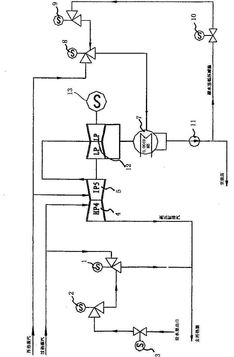
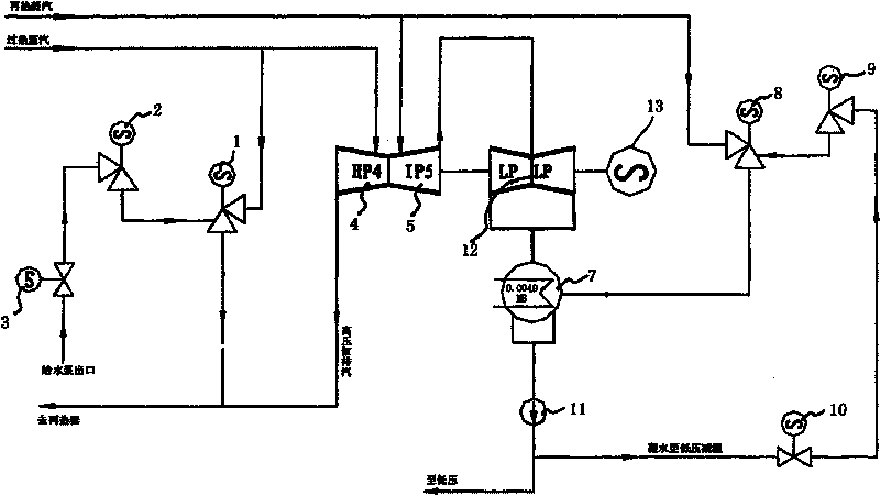
[0019] see figure 1 , a high-low pressure bypass system, including a reheat steam input pipeline, a superheated steam input pipeline, and a feed water pump input pipeline;
[0020] The reheat steam input pipeline is respectively connected to the medium pressure cylinder 5 and the low pressure bypass steam valve 8;
[0021] The superheated steam input pipeline is respectively connected to the high-pressure steam valve 1 and the high-pressure cylinder 4;
[0022] The input pipeline of the feed water pump is connected to the high-pressure water spray isolation valve 3, the high-pressure water spray isolation valve 3 is connected to the high-pressure desuperheating water regulating valve 2, the high-pressure desuperheating water regulating valve 2 ...
PUM
 Abstract
Description
Claims
Application Information