Self-control fluid jet and drainage lift pump

A technology of fluid injection and lifting pumps, which is applied in the direction of injection pumps, pumps, pump control, etc., which can solve the problems of high maintenance and operation costs, long exhaust time, easy corrosion and leakage of bottom valves, etc., so as to save investment, land occupation, and save Electricity and manpower, energy-saving effect is obvious

Inactive Publication Date: 2010-06-16
SHENYANG ANTI CORROSION ALLOY PUMP
View PDF0 Cites 7 Cited by
  • Summary
  • Abstract
  • Description
  • Claims
  • Application Information

AI Technical Summary

Problems solved by technology

[0003] 1. Ordinary centrifugal pumps are equipped with water ring vacuum pumps: the working principle is to use water ring vacuum pumps to create vacuum conditions for the pump system, so that the medium enters the pump system under atmospheric pressure and then starts the pump to drain water. The disadvantage of this method is that The gas time is long, the service life of the equipment is low, the failure rate is high, and it is not suitable for the special working conditions of acid, alkali, and salt chemical products, etc.
[0004] 2. Self-priming pump: Its working principle is to use the pre-stored medium in the pump cavity under the action of the pump to wrap and discharge the air in the suction pipe during the internal circulation process before it can operate normally. The disadvantage is the exhaust time Long, narrow performance range, low efficiency
[0005] 3. Building a low-level pump room or a high-level reservoir: its working principle is to use the potential difference to create an inlet pressure head for the pump. The disadvantages are that the infrastructure investment is large, the floor area is large, and the maintenance of equipment is difficult. The above-mentioned technological measures all exist The problem that the equipment must be kept warm and heated in winter
[0006] 4. The bottom valve is installed at the suction port of the pump: after the pump is filled with water before running, it starts to run. The disadvantage is that the bottom valve is easy to corrode and leak, so it must be replaced frequently
[0007] 5. Vertical mixed-flow pumps, axial-flow pumps, and swirl pumps are used, and the pumps are inserted into the liquid for use. Since the pumps are all large-scale pumps, heavy and long, large-scale hoisting equipment is required for maintenance and installation, which is difficult to maintain and expensive to maintain and operate.

Method used


Image

  • Self-control fluid jet and drainage lift pump
  • Self-control fluid jet and drainage lift pump
  • Self-control fluid jet and drainage lift pump

Examples


Embodiment 1

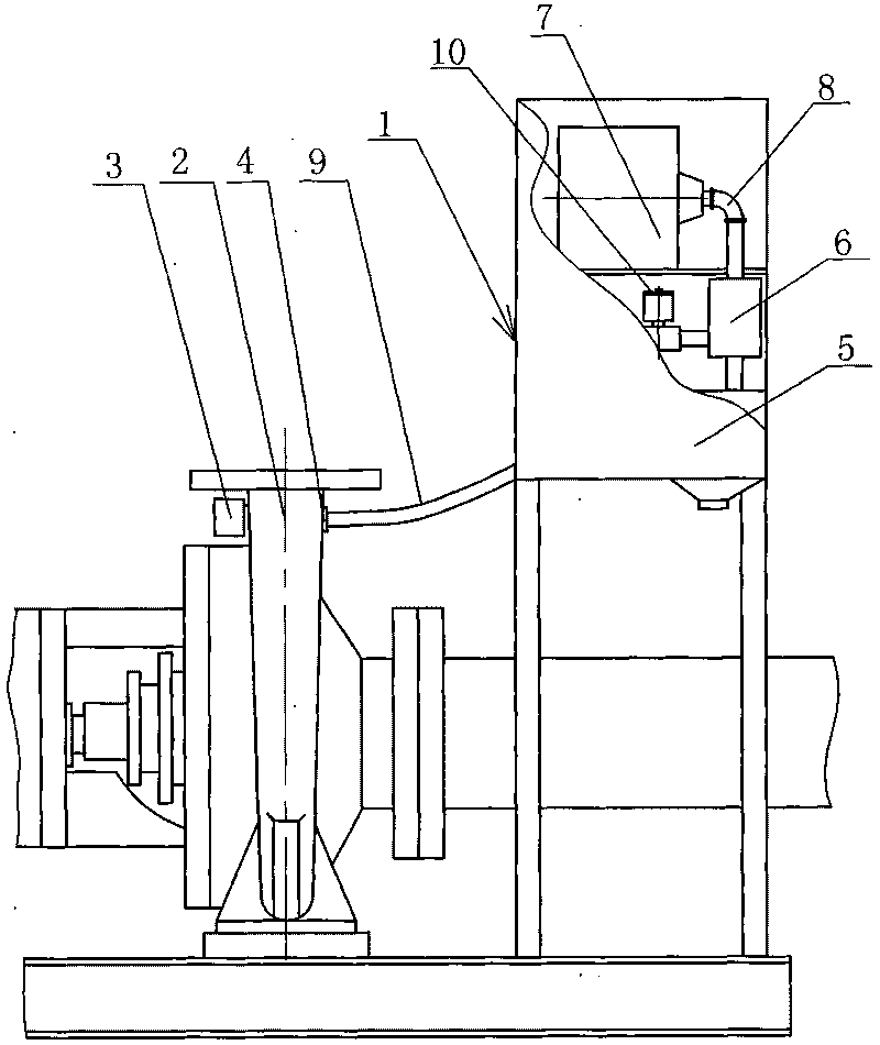
[0031] See figure 1 , the self-controlled fluid jet drainage lifting pump, including the fluid jet drainage device 1, the delivery pump 2 and the liquid level sensor 3 arranged on the delivery pump 2. The upper part of the delivery pump 2 is provided with an exhaust hole 4 that communicates with the inner cavity of the delivery pump 2. The fluid jet drainage device 1 is mainly composed of a housing 5 , a fluid vacuum ejector 6 and a fluid booster 7 arranged in the housing 5 . The fluid booster 7 is communicated with the fluid vacuum ejector 6 through the connecting pipe 8 , and the power fluid of the fluid vacuum ejector 6 comes from the fluid booster 7 built in the fluid ejection and drainage device 1 . A vacuum suction pipe 9 is drawn out from the fluid vacuum ejector 6 , and a vacuum solenoid valve 10 is installed on the vacuum suction pipe 9 .

Embodiment 2

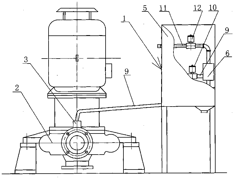
[0033] See figure 2 , the second embodiment is basically the same as the first embodiment, the difference is that the delivery pump 2 is a single-suction horizontal type, the fluid jet drainage device 1 is an external power type, the pressure fluid comes from the outside of the equipment, and the fluid vacuum ejector 6 is directly connected to an external The pressure fluid input pipe 11 is connected to each other, and an external pressure fluid valve 12 is installed on an external pressure fluid input pipe 11 .

Embodiment 3

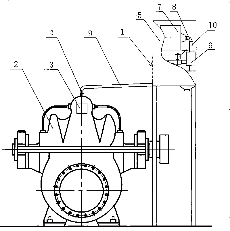
[0035] See image 3 , the third embodiment is basically the same as the first embodiment, the difference is that the delivery pump 2 is a double-suction horizontal type.


PUM


Abstract

The invention discloses a self-control fluid jet and drainage lift pump, which comprises a fluid jet and drainage device and a delivery pump. The delivery pump is provided with a liquid level sensor; and the upper part of the delivery pump is provided with a vent hole which is in gas-tightness connection with the fluid jet and drainage device. Besides the functions of starting in a high liquid level and stopping in a low liquid level, the lift pump is also provided with an intelligent protection shutdown device which enables the lift pump to stop automatically after the medium is completely absorbed, thus, the long-range control can be realized, which can save electricity, manpower and material resources. According to the working condition environment, the vertical, horizontal, movable or fixed installation can be selected. The efficiency is generally improved by 3 to 5 percent, and is 10 to 30 percent higher than that of the traditional unsealed self-control self-suction pump, and the energy saving effect is obvious.

Description

technical field [0001] This patent relates to a pump, in particular to a lift pump that uses fluid jet vacuum technology for drainage. Background technique [0002] Pumps are one of the main equipment for conveying liquid media, and are widely used in petroleum, chemical, electric power, urban construction, environmental protection, sewage treatment, food and pharmaceuticals, synthetic fibers, mining, papermaking, construction, metallurgy, fire protection, tap water and other industrial sectors. At present, the process measures widely used by the pump in the working conditions of suction and discharge of low-level medium are: [0003] 1. Ordinary centrifugal pump is equipped with water ring vacuum pump: its working principle is to use the water ring vacuum pump to create vacuum conditions for the pump system, so that the medium enters the pump system under atmospheric pressure and then starts the pump to drain water. Long gas time, low equipment service life, high failure r...

Claims


Application Information

Patent Timeline
Patent Type & Authority Applications(China)
IPC IPC(8): F04F5/04F04F5/16F04D9/00F04D15/00
CPCF04F5/54F04D9/06
Inventor 郭立新李祥
Owner SHENYANG ANTI CORROSION ALLOY PUMP
Why Eureka
Try Eureka