Shaft kiln

A shaft kiln and kiln chamber technology, applied in the field of shaft kilns, can solve the problems of excessive dust and harmful gas emissions, insufficient fuel combustion, uneven temperature in the furnace, etc. Effect

Inactive Publication Date: 2010-06-16
陈久斌
View PDF0 Cites 6 Cited by
  • Summary
  • Abstract
  • Description
  • Claims
  • Application Information

AI Technical Summary

Problems solved by technology

[0002] Existing shaft kilns are mostly used for producing cement, lime, roasting, and calcining various ores and massive materials, etc., which generally have high energy consumption, insufficient environmental protection emissions, low heat utilization rate, mixed coal combustion in the kiln, and poor fuel combustion. Sufficient, too much dust and harmful gas emissions, uneven temperature in the furnace, etc.

Method used


Image

  • Shaft kiln
  • Shaft kiln
  • Shaft kiln

Examples


Embodiment Construction

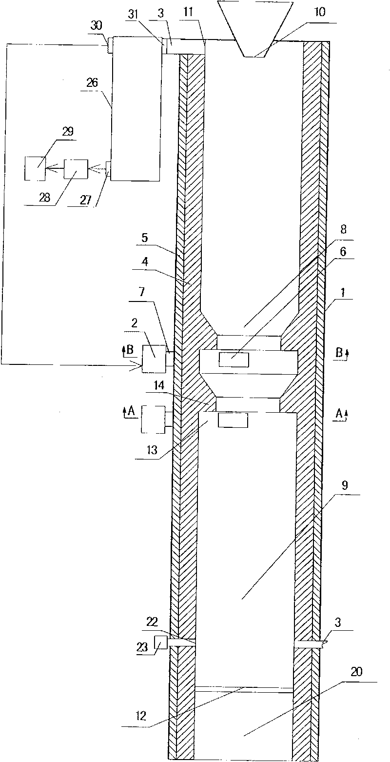
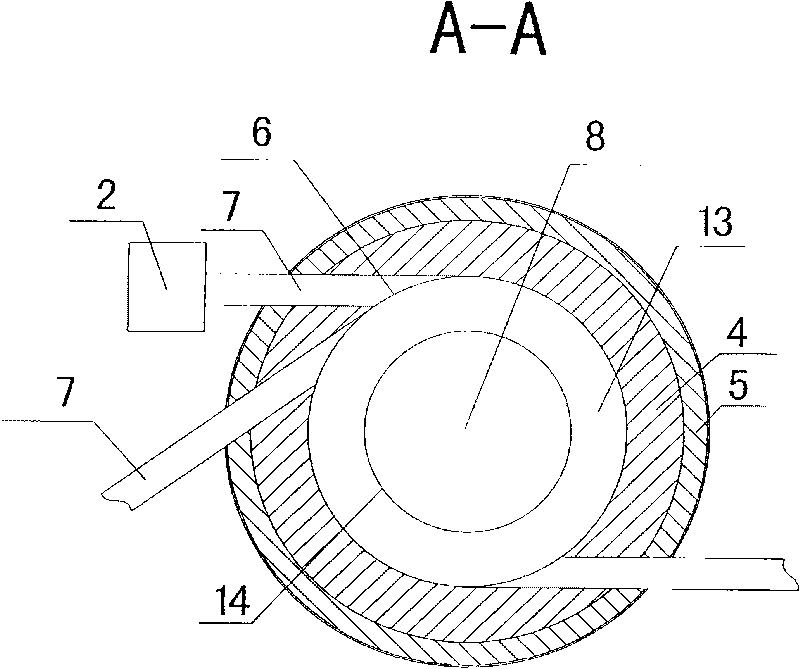
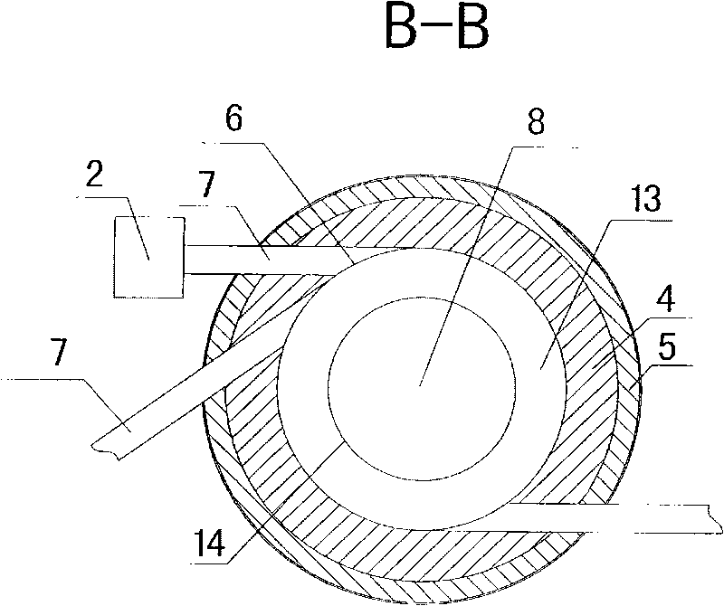
[0023] The main structure of the present invention is: the shaft kiln includes a fuel supply device, an ignition device, a discharge device, a kiln chamber 1, a refractory material 4, an insulating material 5, a fan and a pipeline 3, and at least one air inlet 6 is arranged on the side wall of the kiln chamber 1 , the air inlet 6 is connected to at least one air intake passage 7, the air intake passage 7 is provided with a fan 2, the kiln chamber 1 is provided with a heating chamber 8 and a cooling chamber 9, the lower part of the heating chamber 8 is connected to the cooling chamber 9, and the upper part of the heating chamber 8 is provided with a feed Port 10, heating chamber 8 upper part is provided with heating chamber air outlet 11, cooling chamber 9 lower part is provided with discharge port 12, discharge port 12 is provided with unloading device, on the kiln chamber 1 side wall between heating chamber 8 and cooling chamber 9 at least A fire path 13 is set, and the air in...


PUM


Abstract

The invention discloses a shaft kiln, which comprises a fuel supply device, an ignition device, a discharge device, a kiln chamber, a refractory material, an insulating material, a fan and a pipeline. The side wall of the kiln chamber is provided with at least one air inlet which is at least connected with an air inlet passage. The fan is arranged on the air inlet passage. The kiln chamber is provided with a heating chamber and a cooling chamber, wherein the lower part of the heating chamber is communicated with the cooling chamber; the upper part of the heating chamber is provided with a feed inlet and an air outlet for the heating chamber; and the lower part of the cooling chamber is provided with a discharge outlet. The discharge outlet is provided with the discharge device; and at least one flame path is arranged on the side wall of the kiln chamber between the heating chamber and the cooling chamber, and is communicated with the air inlet. Due to the use of heat convection and vortexes for combustion, the shaft kiln is more energy-saving and environment-friendly. The vortexes are formed in the kiln chamber by using forced air, so that the material is uniformly heated. The movement of hot air around the material replaces a heating mode of rolling the material, and the material naturally moves to a preheating zone, a heating zone, and a cooling zone by using natural sedimentation. The shaft kiln can be applied to burning cement, lime, alumina and other blocked materials.

Description

technical field [0001] The invention relates to the field of kiln equipment, in particular to a shaft kiln. Background technique [0002] Existing shaft kilns are mostly used for producing cement, lime, roasting, and calcining various ores and massive materials, etc., which generally have high energy consumption, insufficient environmental protection emissions, low heat utilization rate, mixed coal combustion in the kiln, and poor fuel combustion. Sufficient, too much dust and harmful gas emissions, uneven temperature in the furnace and other problems. Contents of the invention [0003] The purpose of the present invention is to provide a shaft kiln with a new structure, which can make the fuel burn more fully, the energy utilization rate is higher, the emission is more environmentally friendly, and the harmful gas emission is greatly reduced, which can make the product more excellent, save energy and reduce consumption, and reduce production. The cost is greatly improved...

Claims


Application Information

Patent Timeline
Patent Type & Authority Applications(China)
IPC IPC(8): F27B1/06F27B1/16F27B1/24
Inventor 陈久斌
Owner 陈久斌
Why Eureka
Try Eureka