High bandwidth multimode fiber

A multi-mode optical fiber and high-bandwidth technology, which is applied in the field of optical communication, can solve problems such as the negative impact of multi-mode bandwidth, achieve the effects of simple and effective manufacturing methods, reduce microbend loss, and improve bending resistance

Active Publication Date: 2010-06-16
YANGTZE OPTICAL FIBRE & CABLE CO LTD
View PDF3 Cites 44 Cited by
  • Summary
  • Abstract
  • Description
  • Claims
  • Application Information

AI Technical Summary

Problems solved by technology

However, this type of design will have a significant problem, that is, more high-order mode energy will be con...

Method used


Image

  • High bandwidth multimode fiber
  • High bandwidth multimode fiber
  • High bandwidth multimode fiber

Examples


Embodiment 1

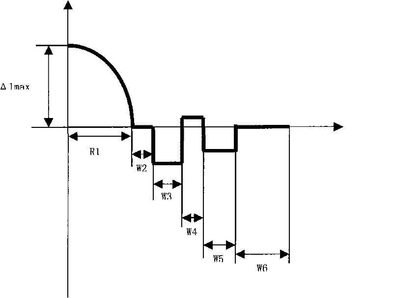
[0045] According to the design of the technical plan (as attached figure 1 Shown), and the manufacturing method of the present invention, prepared a group of prefabricated rods and drawing, adopting the double-layer coating of multimode optical fiber and the drawing speed of 600 m / min, the structure and main performance parameters of the optical fiber are shown in Table 1.

[0046] Table 1

[0047]

[0048]

Embodiment 2

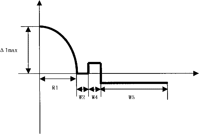
[0050] According to attached figure 2 According to the design and the manufacturing method of the present invention, a group of prefabricated rods were prepared and drawn, using double-layer coating of multimode optical fiber and a drawing speed of 600 m / min. The structure and main performance parameters of the optical fiber are shown in Table 2.

[0051] Table 2

[0052]

[0053]

Embodiment 3

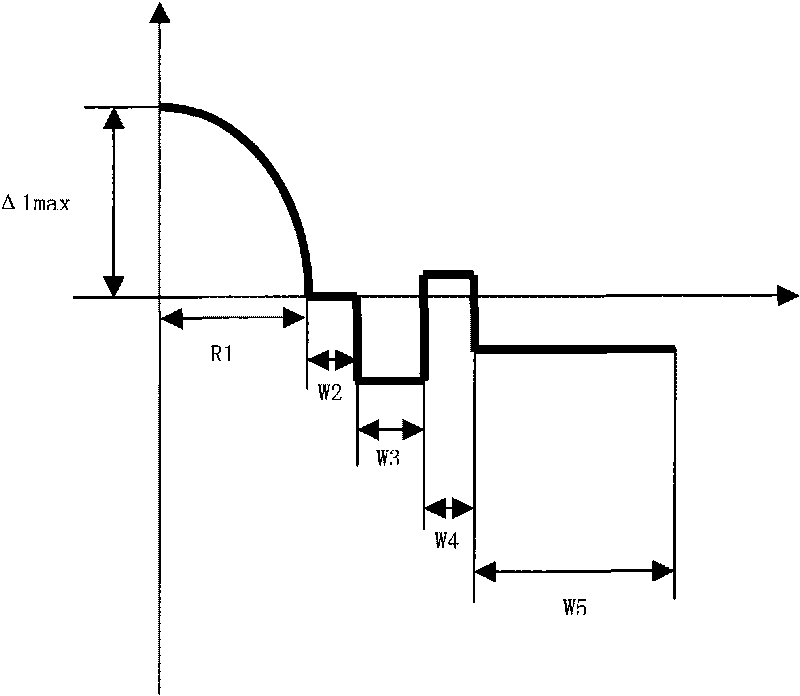
[0055] According to attached image 3 According to the design and the manufacturing method of the present invention, a group of preforms were prepared and drawn, using double-layer coating of multimode optical fiber and a drawing speed of 600 m / min. The structure and main performance parameters of the optical fiber are shown in Table 3.

[0056] table 3

[0057]

[0058]

[0059]

[0060] The optical fiber refractive index profiles of the fourth to eighth embodiments of the present invention are as follows Figure 4-8 As shown, the main difference between the fourth embodiment and the third embodiment is that the relative refractive index difference Δ5% of the depressed outer cladding changes in a curve along the radial direction, and the curve is arc-shaped; the fifth embodiment and the first The main difference between the three embodiments is that the relative refractive index difference Δ5% of the depressed outer cladding is linearly decreasi...


PUM

PropertyMeasurementUnit
Thicknessaaaaaaaaaa
Unilateral thicknessaaaaaaaaaa
Thicknessaaaaaaaaaa

Abstract

The invention relates to a high bandwidth multimode fiber used in an access network and a miniaturized optical device, which comprises a core layer and clad layers. The high bandwidth multimode fiber is characterized in that the radius of the core layer is 15 to 35 microns, the refractive index profile of the core layer is parabolic, and the maximum relative refractive index difference delta 1 percent max is over 0.8 percent; and the clad layers outside the core layer comprise an inner clad layer and/or a sunken inner clad layer, a rising ring and a sunken outer clad layer from the inside to the outside, and the relative refractive index difference of each layer satisfies the following relationships at the same time: delta 1 percent max is more than delta 2 percent which is more than delta 3 percent, delta 4 percent is more than delta 3 percent, the delta 4 percent is more than delta 5 percent, and the delta 4 percent is more than or equal to delta 2 percent. The macro-bending additional attenuation of the fiber is remarkably reduced, and the anti-bending performance of the fiber is improved; the fiber is provided with the rising ring so that the energy of some high-order mode of the core layer of the fiber is transferred or coupled to some mode of the rising ring from the core layer to effectively improve the bandwidth of the bending-insensitive multimode fiber; and the manufacturing method of the invention is simple, convenient and effective, and is suitable for mass production.

Description

technical field [0001] The invention relates to a high-bandwidth multimode optical fiber used in access networks and miniaturized optical devices. The optical fiber has excellent bending resistance and high bandwidth, and belongs to the technical field of optical communication. Background technique [0002] Multimode optical fiber, especially high-bandwidth multimode optical fiber (such as OM3), has been widely used in short- and medium-distance optical fiber network systems (such as data centers and campus networks, etc.) due to relatively low system construction costs. Cabling in indoor and confined environments, especially in applications where excessively long fibers are often wound in increasingly miniaturized storage boxes, is likely to experience tight bend radii. Therefore, it is necessary to design and develop multimode optical fibers with bend-insensitive properties to meet the requirements of indoor optical fiber network laying and device miniaturization. Compare...

Claims


Application Information

Patent Timeline
IPC IPC(8): G02B6/02G02B6/028G02B6/036
CPCG02B6/03666G02B6/0288G02B6/0281
Inventor 张方海韩庆荣拉吉·马泰
Owner YANGTZE OPTICAL FIBRE & CABLE CO LTD
Why Eureka
Try Eureka