
Amorphous alloy transformer core and manufacturing method thereof

A technology of transformer iron core and amorphous alloy, which is used in inductor/transformer/magnet manufacturing, transformer/inductor core, electrical components, etc., can solve the problem of insufficient bonding fastness, affecting the safety of transformer operation, epoxy resin Cracking or peeling problems

Inactive Publication Date: 2010-06-16
CHINESE ELECTRICAL EQUIP GRP CO LTD
View PDF0 Cites 16 Cited by
  • Summary
  • Abstract
  • Description
  • Claims
  • Application Information

AI Technical Summary

Problems solved by technology

Since the amorphous alloy strip and the inner and outer silicon steel sheets are only bonded by a thin layer of adhesive, the bonding fastness is not enough. During the handling of the iron core and (or) the assembly process of the amorphous alloy transformer, It often occurs that the amorphous alloy strip and the silicon steel sheet are peeled off, and the amorphous iron filings will run out from the gap, causing the transformer to be grounded at multiple points or mixed in the transformer oil, causing the transformer to short circuit, etc., seriously affecting the transformer. safe operation of
In addition, the epoxy resin is relatively brittle. During the handling process of the amorphous alloy transformer, the epoxy resin will crack or peel off after being squeezed by the magnetic suspension or bumped during transportation, especially for the three-frame and three-column iron core.

Method used


Image

  • Amorphous alloy transformer core and manufacturing method thereof
  • Amorphous alloy transformer core and manufacturing method thereof
  • Amorphous alloy transformer core and manufacturing method thereof

Examples


Embodiment Construction

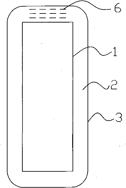
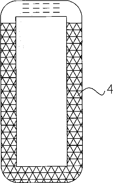
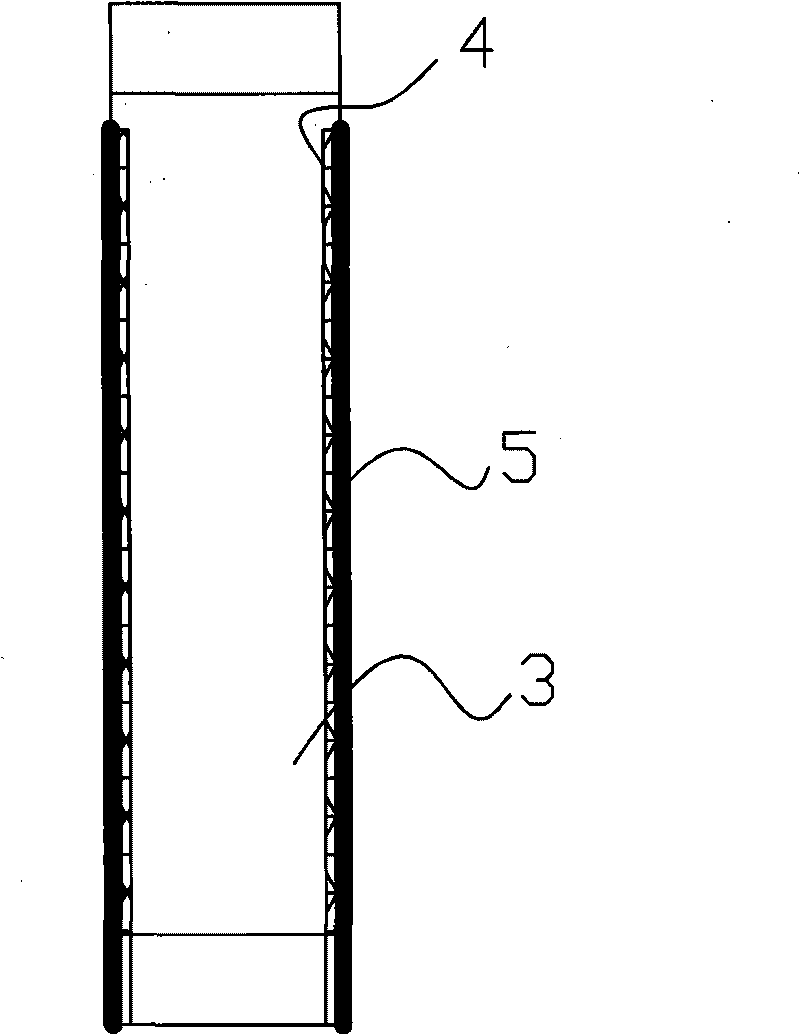
[0035] Such as figure 1 , 2 An amorphous alloy transformer core is shown, which includes a rectangular iron core frame formed by laminating amorphous alloy strips 2. One frame edge of the iron core frame contains a lap head 6, and the innermost layer of amorphous alloy The inner side of the strip 2 is provided with an inner silicon steel sheet 1, the outermost layer of the amorphous alloy strip 2 is provided with an outer layer of silicon steel sheet 3, and the end surface of the laminated seam of the amorphous alloy strip 2 is laid on the iron core frame. Mesh fiber material4. Such as image 3 As shown, the width of the grid fiber material 4 is 20 mm larger than the overlapping thickness of the amorphous alloy strip 2, the inner layer silicon steel sheet 1, and the outer layer silicon steel sheet 3, and each edge of the grid fiber material 4 has a thickness of 10 mm. Covered on the inner silicon steel sheet 1 and the outer silicon steel sheet 3. The grid fiber material 4 ...


PUM


Abstract

The invention discloses an amorphous alloy transformer core, which comprises a rectangular core frame body formed by laminating amorphous alloy strips. An inner side of the amorphous alloy strip on the innermost layer is provided with an inner silicon-steel sheet, and an outer side of the amorphous alloy strip on the outermost layer is provided with an outer silicon-steel sheet. Grid fiber materials are adhered on the end face of the core frame body which is provided with lamination seams of the amorphous alloy strips through insulating glue. The width of the grid fiber materials is greater than the lamination thickness of the amorphous alloy strips, the inner silicon-steel sheet and the outer silicon-steel sheet, and the edges of the grid fiber materials are adhered to the inner silicon-steel sheet and the outer silicon-steel sheet. The invention also discloses a manufacturing method for the amorphous alloy transformer core. By adhering the grid fiber materials, the adhesive strength of a coating is increased; the crack of the coating is prevented; the shed of the amorphous core is prevented; and the safe operation of a transformer is guaranteed.

Description

technical field [0001] The invention relates to an amorphous alloy transformer iron core and a manufacturing method thereof. Background technique [0002] The existing amorphous alloy transformer core is formed by stacking several groups of amorphous alloy strips and then extruded. In order to ensure that the amorphous alloy strips in the amorphous alloy transformer core will not loosen and detach Usually, 0.3 mm silicon steel sheets are used to wrap the inside and outside of the iron core, and the end face of the laminated seam of the amorphous alloy strip on the iron core is cured, sealed and insulated with coating glue or epoxy resin. Since the amorphous alloy strip and the inner and outer silicon steel sheets are only bonded by a thin layer of adhesive, the bonding fastness is not enough. During the handling of the iron core and (or) the assembly process of the amorphous alloy transformer, It often occurs that the amorphous alloy strip and the silicon steel sheet are pe...

Claims


Application Information

Patent Timeline
IPC IPC(8): H01F27/24H01F41/02
Inventor 高昌平周永红王跃林
Owner CHINESE ELECTRICAL EQUIP GRP CO LTD
Learn More