Armature core, motor and axial gap electrical rotating machine using same and method for making same

A technology of armature iron core and axial gap, applied in the field of armature iron core, can solve the problem of difficulty in using a rotating motor, etc., and achieve the effects of preventing rust on the gap surface, reducing iron loss, and simple processing procedures

Inactive Publication Date: 2010-06-16
HITACHI IND EQUIP SYST CO LTD
View PDF6 Cites 42 Cited by
  • Summary
  • Abstract
  • Description
  • Claims
  • Application Information

AI Technical Summary

Problems solved by technology

In mold fixing, it is difficult to use for rotating motors that require high torque or high rotation speed in terms of strength

Method used


Image

  • Armature core, motor and axial gap electrical rotating machine using same and method for making same
  • Armature core, motor and axial gap electrical rotating machine using same and method for making same
  • Armature core, motor and axial gap electrical rotating machine using same and method for making same

Examples


Embodiment 1

[0116] Below, use Figure 1 to Figure 6 An example of the present invention will be described.

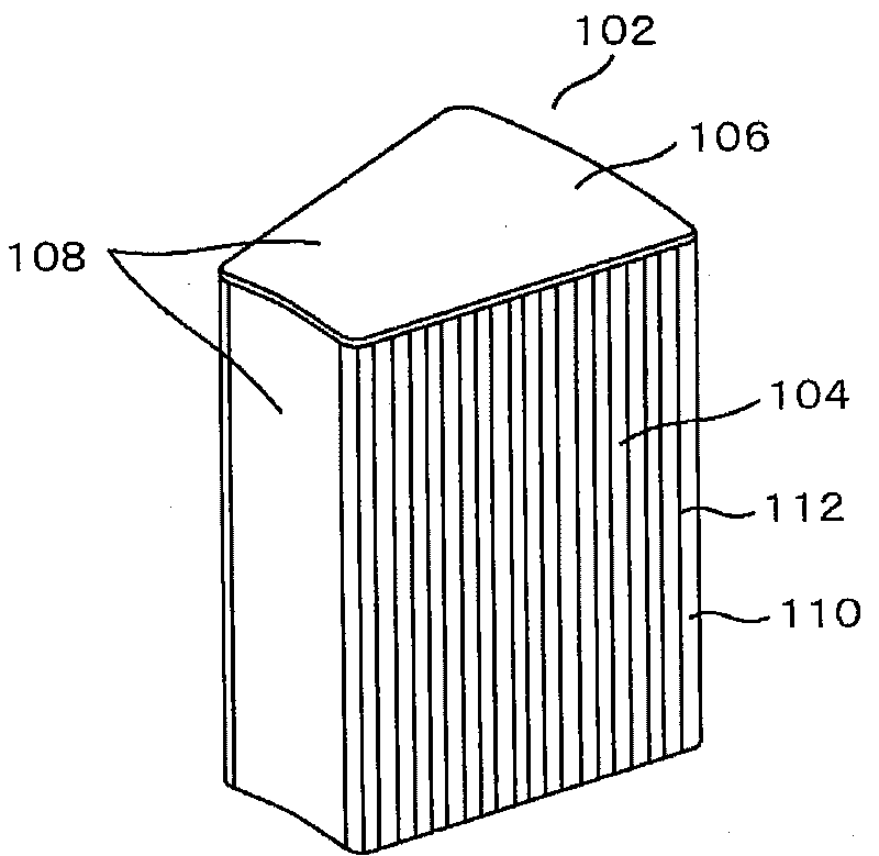
[0117] figure 1 An overall view of the amorphous core 102 as the first embodiment of the present invention is shown.

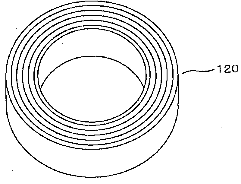
[0118] The core portion 104 of the amorphous core 102 uses a strip-shaped (foil strip) amorphous metal (amorphous metal) 110 as an iron base, and an insulating resin material (hereinafter referred to as resin) 112 is interposed therebetween. In a laminated structure, strip-shaped amorphous metals 110 are respectively fixed with resin.

[0119] In addition, the core portion 104 is fan-shaped when viewed from above and below.

[0120] In the gap surface 106 in the vertical direction of the core part 104, the layer of the resin part 108 made of a very thin resin of 0.3 mm to 0.5 mm is used to prevent the gap surface 106 from rusting. The directional surface and the outer surface are also formed with a layer of the resin part 108 based on the resin to prevent rust. ...

Embodiment 2

[0131] Figure 6 It is a diagram showing an axial gap motor using the amorphous core 102 of the first embodiment. A motor using the amorphous core of this embodiment includes: a stator 304 having a plurality of stator amorphous cores 102 and stator windings 160; and rotors 302, 304 having substantially rhombic ferrite magnets 310. The two rotors 302, 304 have a structure sandwiching the stator 304. In the motor of this embodiment, the stator has 9 poles and the magnet has 6 poles. However, the number of poles of the armature and the number of magnet poles can also be other. combination. In addition, depending on circumstances, the rotor in this embodiment may be set to the fixed side and the stator side may be rotated.

[0132] Figure 7 The detailed shapes of the ferrite magnet 310, the amorphous core 102, and the winding 160 are shown. Figure 7 showing the view from above Figure 6 shape of the motor. In order to reduce the cogging torque, the magnet 310 is provided w...

Embodiment 3

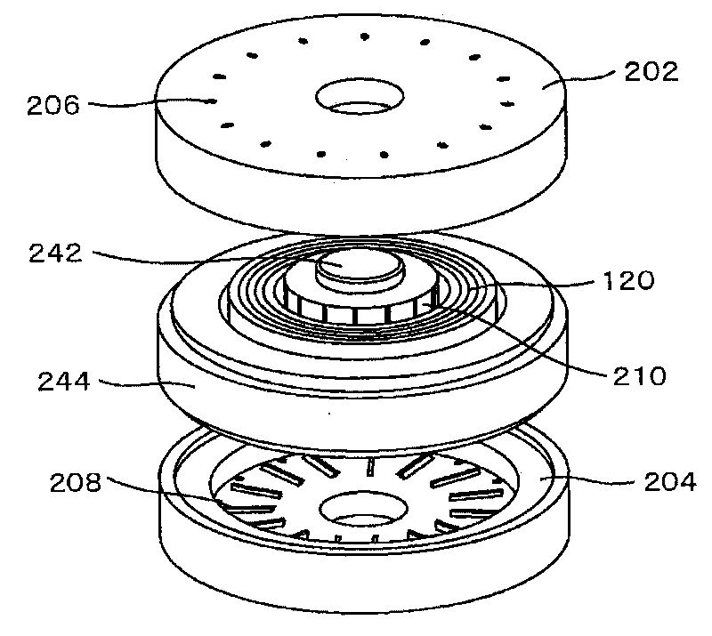
[0143] Figure 12 is a partial cross-sectional perspective view of the rotating electric machine of Embodiment 3, Figure 13 It is an exploded perspective view in which the components of the electric rotating machine according to the third embodiment are developed along the rotor axial direction. Figure 14 It is a structural view of the core holding member which comprises the stator of the electric rotating machine of Example 3, (a) is a perspective view, (b) is a top view.

[0144] Such as Figure 12 As shown, this axial gap type rotating electric machine 501 (hereinafter simply referred to as "rotating electric machine 501") includes a stator 402 and two sides of the rotor shaft 401 in the axial direction of the stator 402 that are arranged opposite to each other with a predetermined gap (gap). A pair of rotors 403A, 403B are accommodated in the casing 404, and the two outer surfaces of the rotor shaft 401 in the axial direction ( Figure 12 The upper and lower outer sur...


PUM


Abstract

A noncrystalline armature core, motor and axial gap electrical rotating machine using same. For the amorphous core, a resin mold is formed, and the peel off is prevented and the gap surface is prevented from rusted. The contact portions between winding wires and amorphous are provided with edge roundness, thus the winding wires can be arranged around the amorphous core. Further, an axial gap motor using cut cores of amorphous lamination as stator cores is provided. Still further, the stator includes: a plurality of stator cores in a bar shape, the stator cores being disposed along circumferential direction, wherein the axial line of the rotor shaft is the central axis of the circumferential direction, and wherein an axial direction of the stator cores is along the axial line direction AXof the rotor shaft; a stator core holding member in a disc form, the stator having a plurality of holes or recessions that are substantially in the same shape as a cross-sectional shape of the statorcores and are arranged along the circumferential direction, wherein the axial line of the rotor shaft is the central axis of the circumferential direction; and coils wound around the stator cores, and wherein the stator cores are inserted in the holes or recessions of the stator core holding member and held by fixing in vicinities of respective central portions thereof, the central portions beingwith respect to the axial direction thereof.

Description

technical field [0001] The present invention relates to an armature core, a motor using the armature core, an axial gap type rotating electric machine (axial gap type motor) having a gap in the axial direction, and a manufacturing method thereof. Background technique [0002] In recent years, a high-efficiency and low-cost rotating electric motor has been pursued from the viewpoint of fuel shortage, environmental pollution, and economy. In addition, it is considered that an amorphous metal is used in this electric rotating machine. Since amorphous metal is a material with excellent magnetic and mechanical properties such as low loss, high magnetic permeability, high strength, and corrosion resistance, it is expected to be used as a motor core to improve the efficiency and cost of the motor. [0003] Commonly used amorphous metals are thin, continuous ribbons of constant width. Regarding methods of manufacturing iron cores from strip-shaped amorphous metals, the prior art i...

Claims


Application Information

Patent Timeline
Patent Type & Authority Applications(China)
IPC IPC(8): H02K1/12H02K15/02H02K1/27H02K21/12
CPCH02K1/14H02K21/24H02K1/2793H02K1/2798
Inventor 王卓男榎本裕治森永茂树正木良三谷川茂穗板桥弘光伊藤元哉
Owner HITACHI IND EQUIP SYST CO LTD
Why Eureka
Try Eureka