Motor control system capable of realizing high-efficiency recovery of kinetic energy and control method thereof

A motor control and high-efficiency technology, applied in motor generator control, control system, electric braking system, etc., can solve the problems of reducing kinetic energy recovery rate, kinetic energy consumption, and limited use of braking voltage, so as to reduce costs, The effect of improving range and efficiency

Inactive Publication Date: 2010-06-16
NANJING UNIV OF SCI & TECH
View PDF0 Cites 3 Cited by
  • Summary
  • Abstract
  • Description
  • Claims
  • Application Information

AI Technical Summary

Problems solved by technology

[0004] 1. The range of step-up and step-down allowed by the DC converter is limited, and the braking voltage is too high or too low to be limitedly utilized. At this time, the kinetic energy can only be consumed on the traditional dynamic brake
[0005] 2. High-power DC converters are not only huge in size, but also costly
And the wider the voltage range, the larger the volume of the inductance element required, and the higher the cost
[0006] 3. There is power loss in the DC converter itself, which greatly reduces the recovery rate of kinetic energy
And the wider the voltage transformation range, the larger the volume of the required inductive element and the higher the loss

Method used


Image

  • Motor control system capable of realizing high-efficiency recovery of kinetic energy and control method thereof
  • Motor control system capable of realizing high-efficiency recovery of kinetic energy and control method thereof
  • Motor control system capable of realizing high-efficiency recovery of kinetic energy and control method thereof

Examples


Embodiment Construction

[0019] The present invention will be described in further detail below in conjunction with the accompanying drawings.

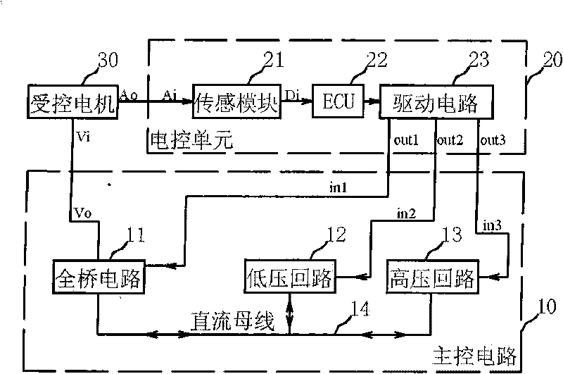
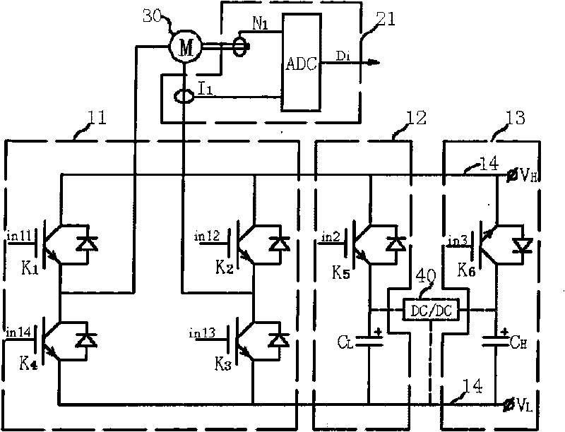
[0020] Depend on figure 1 As shown, a motor control system capable of efficiently recovering kinetic energy of the present invention includes an electronic control unit 20, a main control circuit 10, and a controlled motor 30. The main control circuit 10 includes an H-type full-bridge circuit 11, a low-voltage circuit 12, The high-voltage circuit 13, the above three circuits are connected in parallel through the DC bus 14, and the three input terminals of the main control circuit are the first input terminal in1 of the full-bridge circuit 11, the second input terminal in2 of the low-voltage circuit 12, and the first input terminal of the high-voltage circuit 13. Three input terminals in3; the analog signal input terminal Ai of the electronic control unit 20 is connected to the analog signal output terminal Ao of the controlled motor 30 to obtain the current a...


PUM


Abstract

The invention discloses a motor control system capable of realizing the high-efficiency recovery of kinetic energy, which comprises a electric control unit, a main control circuit, and a controlled motor; wherein the main control circuit comprises an H type full bridge circuit, a lower voltage loop, and a high voltage loop which are mutually connected in parallel through a direct current bus, and three input ends of the main control circuit are respective a first input end of the full bridge circuit, a second input end of the lower voltage loop, and a third input end of the high voltage loop; an analog signal input end of the electric control unit is connected to an analog signal output end of the controlled motor; the first output end of the electric unit is connected with the first input end of the full bridge circuit, the second output end of the electric control unit is connected with the second input end of the lower voltage loop, and the third output end of the electric control unit is connected with the third input end of the high voltage loop; and the voltage end of the full bridge circuit is the output end of the main control circuit. Without using large power direct current converter, the invention can improve the range and the efficiency of the kinetic energy with the help of the afterflow effect of per se inductance of the motor.

Description

technical field [0001] The invention relates to a motor control system and a control method thereof, in particular to a motor control control system and a control method thereof capable of realizing efficient recovery of kinetic energy. Background technique [0002] The electric vehicle uses the motor as the power device, and the motor control system controls the motor to output a certain torque and speed according to the instructions. In order to maximize the mileage of the vehicle on one charge, the motor control system must not only ensure the high performance of the motor in the electric state, but also ensure the efficient regenerative power generation performance of the motor in the braking state. [0003] At present, electric vehicles mainly use two speed regulation schemes of DC chopping and AC frequency conversion. In theory, both solutions can recover kinetic energy and feed it back to the electric energy storage system when the vehicle is going downhill or decele...

Claims


Application Information

Patent Timeline
Patent Type & Authority Applications(China)
IPC IPC(8): H02P3/18B60L7/14
CPCY02T10/642Y02T10/64
Inventor 徐照平常思勤
Owner NANJING UNIV OF SCI & TECH
Why Eureka
Try Eureka