Supercharge Your Innovation With Domain-Expert AI Agents!

Powder spray marking device of cutting machine

A scribing device and cutting machine technology, applied in the direction of feeding device, automatic control device, metal processing machinery parts, etc., can solve the problems of scribing and cutting line deviation, difficulty, cutting line and powder spraying line can not overlap, etc., to achieve Effects of reducing shaking, avoiding deviation, increasing speed and shipbuilding precision

Inactive Publication Date: 2010-06-23
YANGFAN GROUP
View PDF2 Cites 3 Cited by
  • Summary
  • Abstract
  • Description
  • Claims
  • Application Information

AI Technical Summary

Problems solved by technology

It also relates to a numerical control cutting control method, the method includes the laser marking machine storing and running the marking machine control file; the numerical control cutting machine storing and running the cutting instruction file at the same time; the numerical control cutting machine moving the X and Y axis moving mechanism according to the cutting instruction file , move the laser marking head to the target area, and send a notification signal to the laser marking machine; the laser marking machine responds to the notification signal, and executes the marking machine control file to automatically mark or draw lines from the target area; the device The scribing in is carried out by the control file of the laser marking machine, the structure is complex and not easy to use in shipbuilding, and there are certain deviations between the scribing and cutting lines
[0004] The problem that causes the biggest deviation is whether the centerline of the cutting gun and the centerline of the powder spraying gun remain unchanged. However, due to human reasons and accidents, one of them has an irregular offset, so that the cutting line and the powder spraying line cannot overlap. , resulting in a large deviation

Method used


Image

  • Powder spray marking device of cutting machine
  • Powder spray marking device of cutting machine
  • Powder spray marking device of cutting machine

Examples


Embodiment Construction

[0015] The present invention will be further described in detail below in conjunction with the accompanying drawings and embodiments.

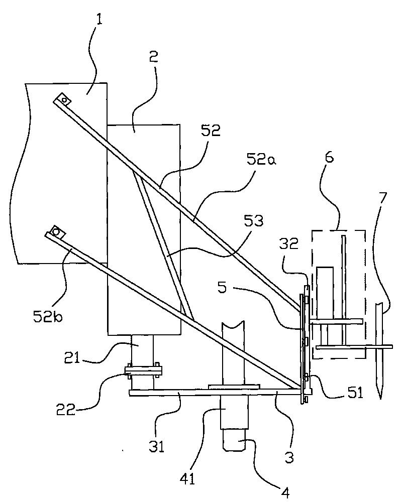
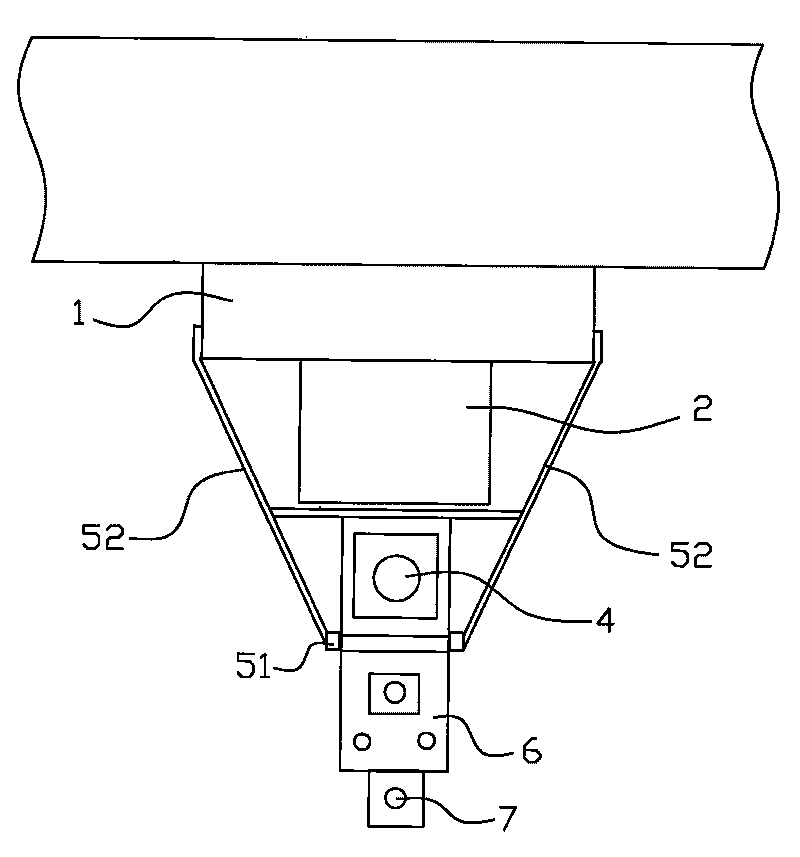
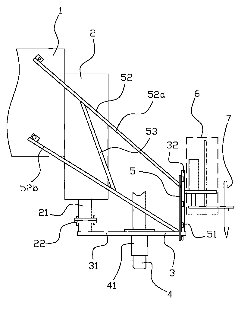
[0016] Such as figure 1 and figure 2 As shown, the powder spraying and scribing device of the cutting machine in this embodiment includes a cutting gun 4 , a powder spraying gun 7 and a lifter 2 , and the lifter 2 is fixed to the trolley 1 . The powder spraying gun 7 is arranged in the powder spraying device 6, and the cutting gun 4 is arranged in the supporting plate 3, and one end of the supporting plate 3 is connected with the lifting shaft 21 which can move up and down in the lifter 2 through the cast iron flange 22. Connect, and the other end of pallet 3 is connected with powder spraying device 6. The powder spraying and scribing device also includes a positioning frame, which is two vertically arranged track bars 5, and the two track bars 5 are fixed to the corresponding two sides of the walking trolley 1 through the fixing bars 52 re...


PUM


Abstract

A powder spray marking device of a cutting machine comprises a cutting gun (4), a powder spray gun (7) and an elevator (2). The cutting gun (4) is arranged in a support plate (3), one end of the support plate (3) is connected with an elevating shaft (21) capable of moving up and down in the elevator (2), and the other end of the support plate (3) is connected with a powder spray device (6). The powder spray marking device also comprises a locating rack, the locating rack consists of two rail rods (5) vertically arranged, the rail rods (5) are respectively fixed with the two sides of a travelling trolley (1) by fixing rods (52), the support plate (3) is arranged between the rail rods (5), and the two sides of the support plate (3) and the relative parts of the rail rods (5) can be arranged together in a vertically sliding mode. Compared with the prior art, the present invention has the advantages that the powder spray marking device is improved by additionally arranging one locating rack, namely auxiliary rail rods, the sway of the cutting gun and the powder spray gun is reduced, and the deviation of cutting lines and powder spray lines is avoided to make the cutting lines and the powder spray lines keep in one line, so the plate splicing speed and the ship building accuracy are improved, production progress is accelerated, and the production efficiency is improved.

Description

technical field [0001] The invention relates to a powder spraying and scribing device for a cutting machine. Background technique [0002] Existing powder spraying marking device on the market at present, as the Chinese patent No. 89207178.8 discloses a kind of marking device for CNC cutting machine, it is made up of sleeve, compression spring, loose block, marking needle and nut , which is characterized in that the scribing needle is detachably connected with the loose block and is in a precise sliding fit with the nut. The loose block is always in contact with the inner spring of the sleeve. The scribing needle can also be replaced by a pen. This device can be installed in the cutting The part of the machine cutting torch can also be installed in other parts where the marking is convenient; the structure of the device is simple, but there is a large deviation between the powder spraying marking line and the cutting line, which makes the accuracy not high. [0003] Another...

Claims


Application Information

Patent Timeline
IPC IPC(8): B23Q15/22B25H7/04
Inventor 万小华黄永海王培海林杰乐建康
Owner YANGFAN GROUP
Features
  • R&D
  • Intellectual Property
  • Life Sciences
  • Materials
  • Tech Scout
  • Unparalleled Data Quality
  • Higher Quality Content
  • 60% Fewer Hallucinations
Learn More