Electro-rheological pendulum shaft cylindrical polishing device

A polishing device and electrorheological technology, applied in surface polishing machine tools, grinding/polishing equipment, metal processing equipment, etc. speed, improved material removal efficiency, and the effect of avoiding power line breakage

Inactive Publication Date: 2011-08-31
BEIJING INSTITUTE OF TECHNOLOGYGY
View PDF0 Cites 0 Cited by
  • Summary
  • Abstract
  • Description
  • Claims
  • Application Information

AI Technical Summary

Problems solved by technology

[0005] The purpose of the present invention is to solve the problems of low material removal rate and difficult integration of the positive and negative electrodes of the traditional needle-shaped electro-rheological polishing tool, and propose an electro-rheological pendulum shaft cylindrical polishing device

Method used


Image

  • Electro-rheological pendulum shaft cylindrical polishing device
  • Electro-rheological pendulum shaft cylindrical polishing device
  • Electro-rheological pendulum shaft cylindrical polishing device

Examples


Embodiment Construction

[0026] The specific implementation manner of the present invention will be described in detail below in conjunction with the accompanying drawings.

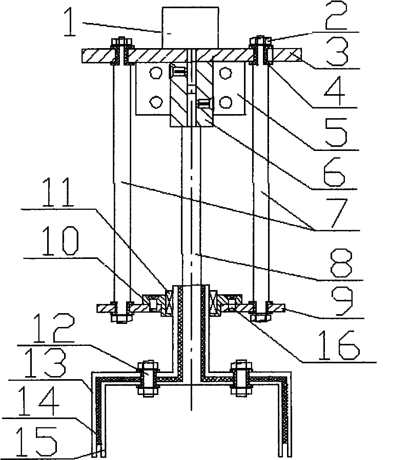
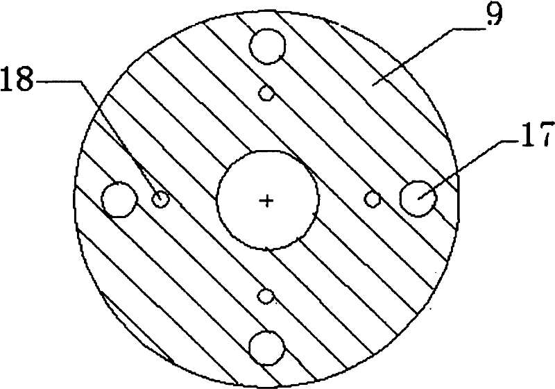
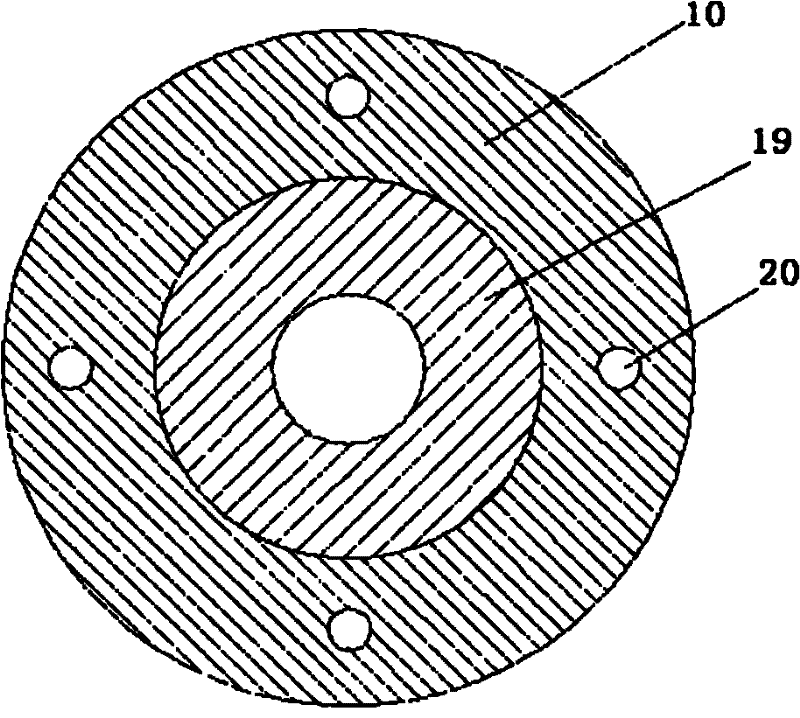
[0027] Such as figure 1 As shown, it is a schematic cross-sectional structure diagram of an electrorheological pendulum cylinder polishing device of the present invention, as can be seen from the figure, it mainly consists of a motor 1, a nut 2, a bracket seat 3, an insulating sleeve 4, and an adapter plate 5 , coupling 6, connecting rod 7, rotating shaft 8, base 9, brush cover 10, ring brush 11, bolt 12, anode polishing cylinder 13, insulating cylinder 14, cathode polishing cylinder 15, screw 16 Composition; the motor 1 is installed on the support base 3 through positioning slots and screws; the support base 3 is fixed on the ultra-precision CNC machine tool through the adapter plate 5 on it, so as to control the movement of the support base according to a certain track; the upper end of the rotating shaft 8 passes through Coup...


PUM


Abstract

The invention belongs to the field of ultra-precise optical surface machining tools, and relates to an electro-rheological pendulum shaft cylindrical polishing device. The polishing device comprises a motor, a bracket seat, a connecting rod, a rotating shaft, a base, a circular electric brush, anode and cathode polishing devices and a hard insulating material, wherein the motor is arranged on thebracket seat; one end of the rotating shaft is connected with a rotating shaft of the motor through a shaft coupling, while the other end is fixed with the cathode polishing device; during polishing,the rotating shaft and a workpiece shaft form a certain angle; the anode and cathode polishing devices and the hard insulating material are fixed together to form an integrated electrode polishing head; a bracket and the base are fixed through the connecting rod; an electric brush sleeve is fixed on the base by bolts; the circular electric brush is placed in a groove of the electric brush sleeve and is tightly contacted with the upper end of the anode polishing device; and during working, the electro-rheological fluid is gathered at the edge of the integrated electrode polishing head to implement polishing when the electro-rheological fluid and a workpiece are contacted and produce relative motion. The anode and the cathode of the polishing device can rotate integrally, and the rotating shaft can swing randomly, so the polishing device is applicable to definiteness machining for complex optical surfaces.

Description

technical field [0001] The invention relates to a polishing device, in particular to an electrorheological pendulum shaft cylindrical polishing device, which belongs to the field of ultra-precision optical surface processing tools. Background technique [0002] With the rapid development of the optoelectronic industry, the quality requirements for the optical components used are getting higher and higher, which promotes the research on optical component processing devices. The traditional optical polishing method relies entirely on manual asphalt polishing based on cerium oxide polishing fluid. This polishing process is non-repeatable, non-deterministic, and takes a long time and is uncertain. In the new century, computer-controlled optical surface shaping (CCOS), stressed lap polishing (Stressed Lap Polishing), ion beam polishing (Ion Polishing), and magnetorheological polishing (MRF) technologies have developed rapidly. Computer-controlled optical surface forming technolo...

Claims


Application Information

Patent Timeline
Patent Type & Authority Patents(China)
IPC IPC(8): B24B29/04
Inventor 程灏波文永富冯云鹏
Owner BEIJING INSTITUTE OF TECHNOLOGYGY
Why Eureka
Try Eureka