Method and device for smelting iron in arc furnace
A technology of electric arc furnace and furnace body, which is applied in the field of smelting ironmaking, can solve the problems of unusable chemical energy and achieve the effects of low heat loss, flexible operation and improved heating efficiency
- Summary
- Abstract
- Description
- Claims
- Application Information
AI Technical Summary
Problems solved by technology
Method used
Image

Examples
Embodiment 1
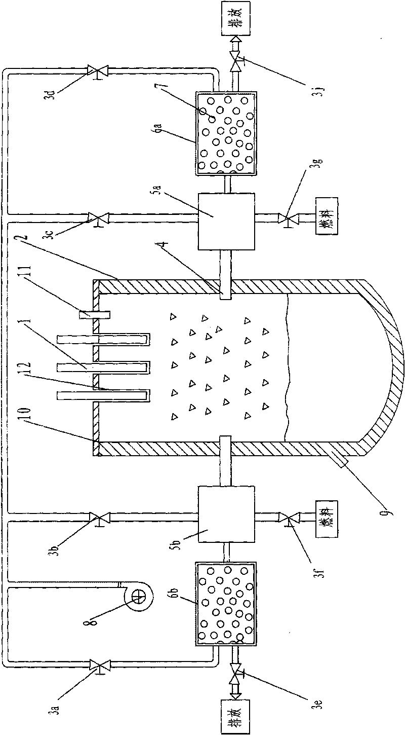
[0027]The device of electric arc furnace melting ironmaking described in the present invention is as figure 1 As shown, it includes a furnace body 2, a furnace cover 10, a feeding device and a discharging device, and a molten iron outlet 9 is provided at the lower part of the furnace body 2. Such as Figure 5 As shown, there are three electrode jacks 12 on the furnace cover 10, which are respectively inserted into the electrodes 1, and the three electrode jacks are distributed in a triangle. A pair of heating furnaces 5a, 5b and a pair of regenerators 6a, 6b outside the furnace body 2 are installed on both sides of the furnace body 2 in relative positions. The heating furnace is connected to the furnace body 2 of the electric arc furnace through a connection port 4, and the gas in the connection port can flow back and forth. One end of the regenerators 6a, 6b is connected to the heating furnace, and the other end is respectively connected to the blower 8 and the exhaust syst...
Embodiment 2
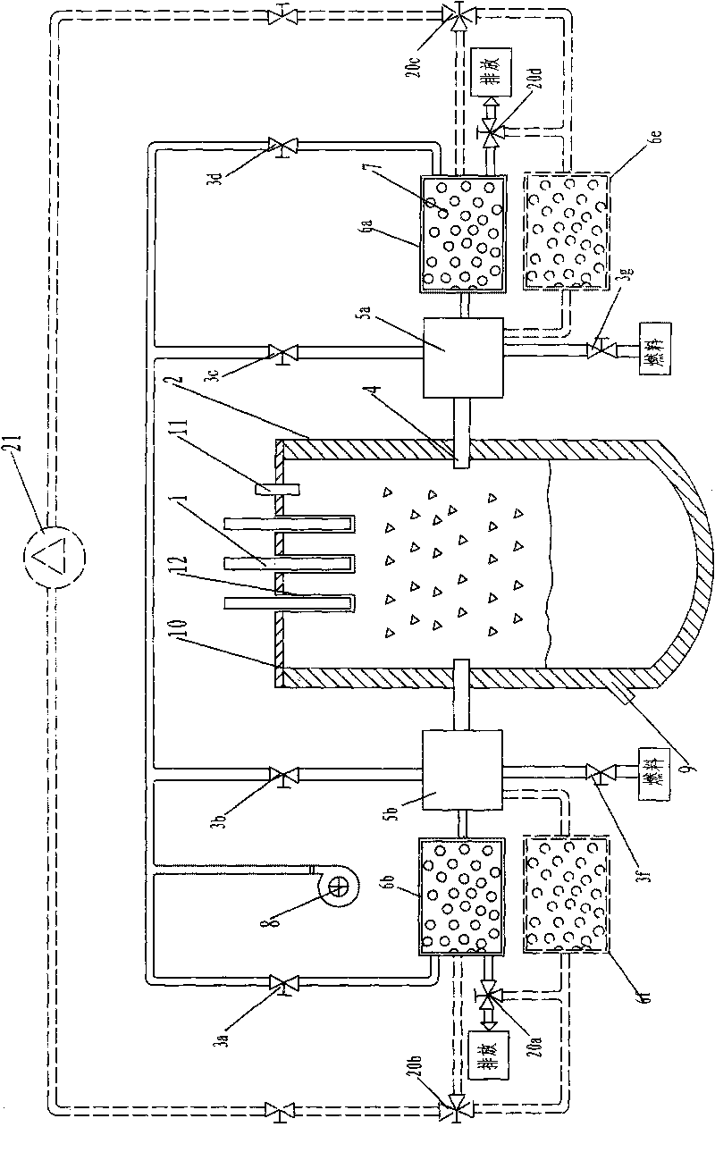
[0032] As an option, such as figure 2 As shown, on the basis of Embodiment 1, the device is also provided with a spare gas treatment device 21 and spare heat accumulators 6e, 6f. The gas treatment device includes a circulating pressurized fan, purification and cooling treatment equipment and a gas storage tank; the gas treatment device 21 is connected to the heat accumulators 6a, 6b, 6e, 6f through three-way valves from both ends, and the heat accumulators 6b, One end of 6f is connected to the heating furnace 5b, and one end of the regenerators 6a and 6e is connected to the heating furnace 5a. The other ends of the heat accumulators 6a and 6b are divided into three paths, one path is connected to the blower 8, one path is connected to the gas treatment device 21 through the three-way valve 20b or 20c respectively, and one path is connected to the discharge system through the three-way valve 20a or 20d respectively. The other ends of the heat accumulators 6e and 6f are divide...
Embodiment 3
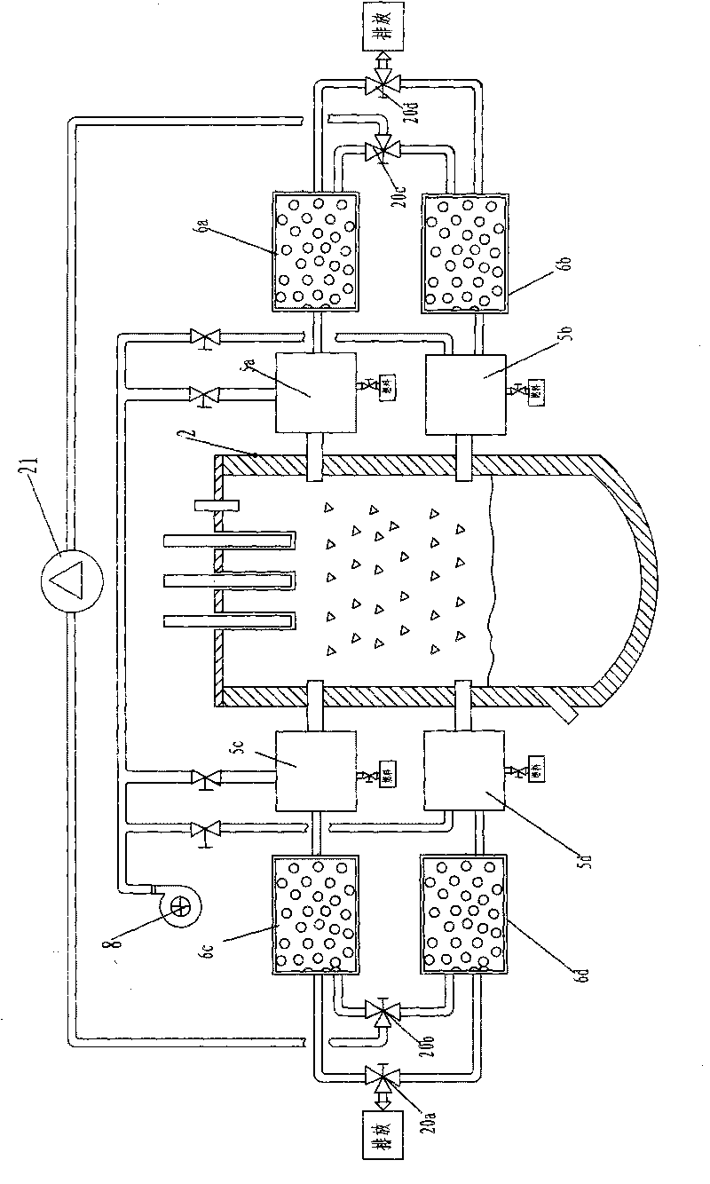
[0034] Another embodiment of the present invention is as image 3 As shown, it includes electric arc furnace and supporting equipment, 4 heating furnaces (5a, 5b, 5c, 5d), 4 regenerators (6a, 6b, 6c, 6d) and gas treatment device 21. Heating furnace and regenerator are installed on the both sides of body of heater 2, and every side two heating furnaces and two regenerators are installed by up and down position. The connection mode of body of furnace, heater is the same as embodiment 1. One end of each regenerator is connected to the heating furnace respectively, and the two outlets at the other end are respectively connected to two three-way valves 20a, 20b and 20c, 20d), and the other ends of the three-way valves 20b, 20c are respectively connected to the gas treatment device 21 The other ends of the three-way valves 20a and 20d are respectively connected to the discharge system. The regenerators 6c and 6d are connected to the gas treatment device through the three-way valve...
PUM
 Abstract
Description
Claims
Application Information
 - Generate Ideas
- Intellectual Property
- Life Sciences
- Materials
- Tech Scout
- Unparalleled Data Quality
- Higher Quality Content
- 60% Fewer Hallucinations
Browse by: Latest US Patents, China's latest patents, Technical Efficacy Thesaurus, Application Domain, Technology Topic, Popular Technical Reports.
© 2025 PatSnap. All rights reserved.Legal|Privacy policy|Modern Slavery Act Transparency Statement|Sitemap|About US| Contact US: help@patsnap.com