Impulse sensor with damper for actively measuring linear displacement

A technology of active measurement and linear displacement, applied in the direction of measuring devices, instruments, electrical devices, etc., can solve the problems of difficult and fast automatic measurement, low efficiency, incompetence, etc., and achieve the effect of easy mass production, simple assembly and mature technology

Inactive Publication Date: 2010-06-23
涂成生
View PDF0 Cites 9 Cited by
  • Summary
  • Abstract
  • Description
  • Claims
  • Application Information

AI Technical Summary

Problems solved by technology

In practice, it is often necessary to install the workpiece horizontally, so it is difficult to realize fast automatic measurement with the existing digital display gauge sensor
Especially when measuring large and complex workpieces, the number of measuring points is as many as dozens or even hundreds, and the efficiency of the traditional method is obviously low and incompetent

Method used


Image

  • Impulse sensor with damper for actively measuring linear displacement
  • Impulse sensor with damper for actively measuring linear displacement
  • Impulse sensor with damper for actively measuring linear displacement

Examples


Embodiment 1

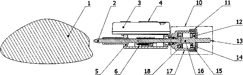
[0022] Embodiment 1 of an active measuring linear displacement sensor with damping pulse type of the present invention is that the push-pull action of the measuring rod is driven by an electromagnet, such as figure 1 As shown, outside the guide hole on the right side of the base 5, the drive assembly 10 is installed. The drive assembly 10 includes a housing 17, an electromagnet coil 18, a piston 12, an end cover 11, and a sealing ring 15. The structure of the piston 12 also includes an integrated The inlaid iron sleeve 14, the ejector rod 16, the moving rod 13, the casing 17 and the base 5, the casing 17 and the end cover 11 are threaded, the casing 17 and the ejector rod 16, the moving rod 13 and the end cover There is a micro-gap sliding fit between the covers 11 .

[0023] The working process of this embodiment is: the external controller gives a trigger signal, the electromagnet coil 18 is energized, the piston 12 moves to the left, the push rod 16 pushes the measuring rod...

Embodiment 2

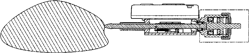
[0025] like Figure 4 It is a schematic diagram of the structure of the driving assembly of the second embodiment of the present invention, which adopts pneumatic drive. The driving assembly includes a cylinder 19, a piston 12, a ported end cover 20, and a sealing ring 15. The structure of the piston 12 also includes a push rod 16, a manual rod 13, and an end The cover 20 is provided with an air inlet 21, the cylinder 19 and the base 5, the cylinder 19 and the end cover 20 are threaded, the cylinder 19 and the ejector rod 16, and the manual rod 13 and the end cover 20 are small gaps. Sliding fit, the air inlet 21 communicates with the air source.

[0026] The working process of this embodiment is: the external controller gives a trigger signal, the air source is connected, the piston 12 moves to the left, the ejector rod 16 pushes the measuring rod 2 against the workpiece 1 to obtain the measured value, and the external controller controls to cut off the air supply. source, t...

Embodiment 3

[0028] like Figure 4 , using hydraulic drive, the composition of the drive components is similar to that of pneumatic, but the sealing performance is higher, and sealing rings should be added between the manual rod 13 and the cylinder end cover 20, the piston 19 and the ejector rod 16. The power source is a hydraulic pump. The control and measurement principles are the same as those in Embodiment 1 and Example 2.


PUM


Abstract

The invention discloses an impulse sensor with a damper for actively measuring linear displacement, which comprises a base, a measuring rod, a control circuit, and a drive component. The impulse sensor is characterized in that: after sending an instruction to the drive component, the measuring rod extends forwards to contact with a measured workpiece; the control circuit acquires a measuring point position (namely, a displacement value) through measuring the amount of movement of the measuring rod; the measuring rod completes the extension action to contact the measured object, pauses and automatically retracts to an initial state to finish a measuring cycle; and the measuring value is maintained in the measuring cycle so as to display, read or upload to an external circuit for further processing. The whole measuring process can be finished under the control of the external circuit. The power of the drive component can be electromagnetic, pneumatic or hydraulic and in other modes. A damper is arranged in the sensor for reducing the measuring oscillation. The impulse sensor has the characteristics of actively extending, automatically measuring, maintaining the numerical reading, and the like. Batch measurement or on-line automatic rapid measurement of the measured object can be realized. A plurality of the sensors can build a large-scale automatic error measurement system.

Description

(1) Technical field [0001] The invention relates to an electronic measurement device for size errors in the field of mechanical manufacturing that can be used for automatic or manual measurement, in particular to a linear displacement sensor with damping pulse type active measurement. (1) Background technology [0002] At present, the length measurement tools used in the field of machinery manufacturing are mainly digital display indicators or rulers based on capacitance linear displacement sensors. Among them, the scales widely used in inspection tools and on-site measurement, such as digital display dial gauges and dial gauges, are all extrapolated, that is, when measuring, the head of the gauge rod continues to contact the workpiece, and the gauge The indicating table shows the measured value of the measured displacement, and the measured data is dynamic. The measuring rod is affected by the internal tension spring, and the state of the measuring rod is always stretched ...

Claims


Application Information

Patent Timeline
Patent Type & Authority Applications(China)
IPC IPC(8): G01B7/02
Inventor 涂成生
Owner 涂成生
Why Eureka
Try Eureka