Diaphragm spring tester

A diaphragm spring and testing machine technology, which is applied in the testing of mechanical components, testing of machine/structural components, measuring devices, etc., can solve the problem of low position control accuracy of hydraulic systems, time delay in hydraulic valve work, and pressure measurement accuracy Reduce and other problems, achieve the effect of improving test efficiency, compact structure, and improving accuracy

Inactive Publication Date: 2010-06-23
SHENYANG INST OF AUTOMATION - CHINESE ACAD OF SCI
View PDF0 Cites 16 Cited by
  • Summary
  • Abstract
  • Description
  • Claims
  • Application Information

AI Technical Summary

Problems solved by technology

However, due to the low precision of the position control of the hydraulic system during the process of driving the lower mold to rise, the hydraulic valve has a time delay after receiving the work command, resulting in a large error in the detection device; Diaphragm springs are tested, and the maximum diameter of the currently detectable diaphragm springs can only reach about 200mm
[0004] In addition, in the existing detection device, the upper mold is prone to generate lateral force during the working process, which leads to a decrease in the accuracy of pressure measurement

Method used


Image

  • Diaphragm spring tester
  • Diaphragm spring tester
  • Diaphragm spring tester

Examples


Embodiment Construction

[0024] The present invention will be described in further detail below in conjunction with the accompanying drawings.

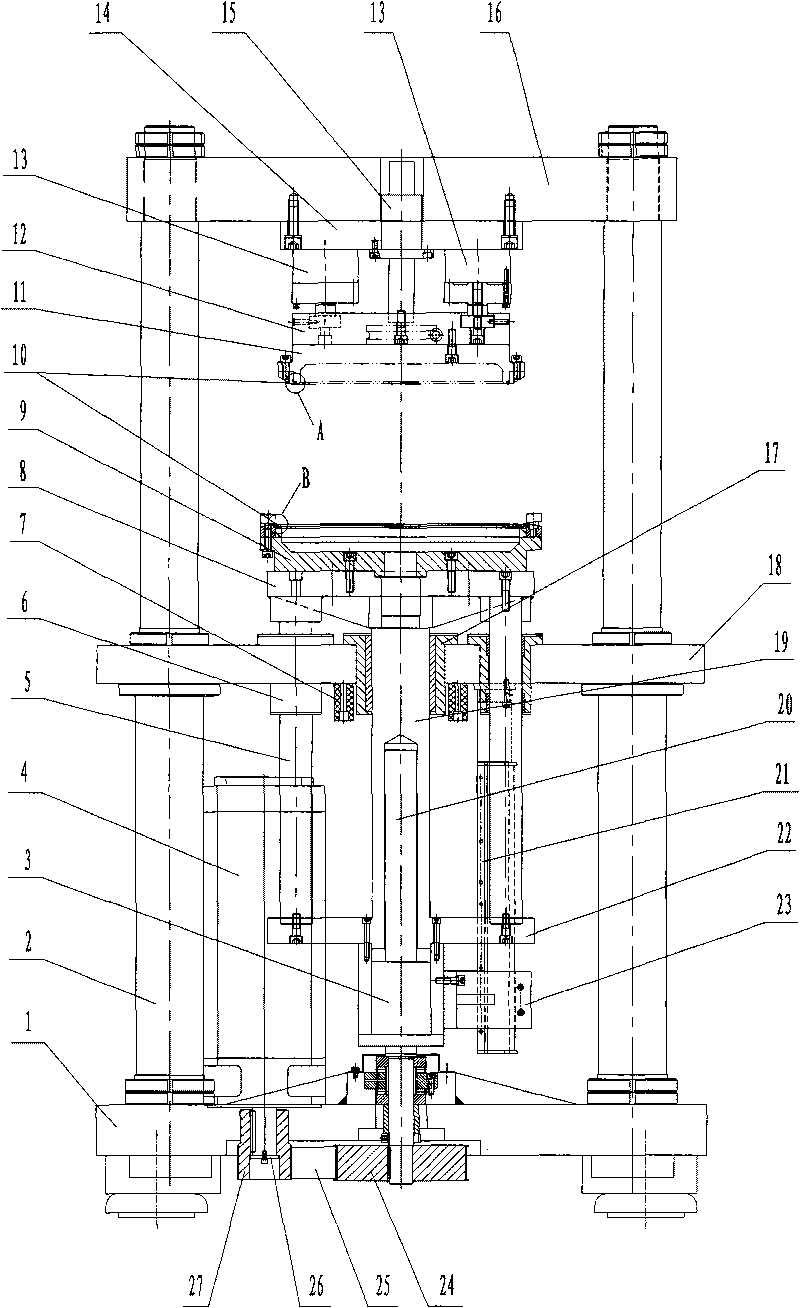
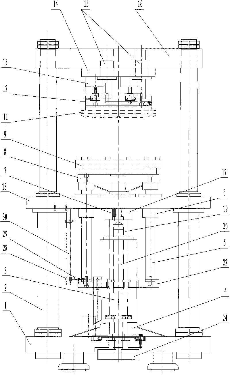
[0025] Such as figure 1 , figure 2 As shown, the present invention comprises fuselage bottom plate 1, screw nut 3, workbench 8, lower mold 9, upper mold 11, fuselage upper plate 16, middle bed plate 18 and ball screw 20, fuselage bottom plate 1, middle bed The body plate 18 and the upper plate 16 of the fuselage are connected through the column 2, the ball screw 20 is installed on the fuselage bottom plate 1, and passes through the fuselage bottom plate 1, and the threading end of the ball screw 20 is key-connected with a first pulley 24 ; Fuselage bottom plate 1 is also provided with motor 4, and the output shaft of motor 4 is worn by fuselage bottom plate 1, and the output end key of output shaft is connected with second pulley 27, and first and second pulley 24,27 pass belt 25 Connect the transmission; the second belt pulley 27 is provided with a pressi...


PUM

PropertyMeasurementUnit
diameteraaaaaaaaaa
diameteraaaaaaaaaa

Abstract

The invention relates to a test mechanism of an automobile clutch diaphragm spring, in particular to a diaphragm spring tester which can effectively measure stress and deformation and detects the load characteristics thereof. The diaphragm spring tester comprises a tester body bottom plate, a nut, a workbench, a low die, a top die, a tester body top plate, a middle lathe bed plate and a ball screw, wherein the tester body bottom plate, the middle lathe bed plate and the tester body top plate are connected by a stand column; the ball screw is installed on the tester body bottom plate and penetrates from the tester body bottom plate to be connected with an actuating device; the nut in threaded connection with the ball screw is provided with a sleeve; the revolute pair of the ball screw is in threaded connection with the nut by the ball screw to form the upper sliding pair and the lower sliding pair of the sleeve; the other end of the sleeve passes through the middle lathe bed plate to be connected with the workbench; the workbench is provided with the lower die; the top die is installed on the tester body top plate and is above the lower die; and the tester body top plate is provided with a pressure sensor contacting with the top die. The invention has the advantages of high efficiency, high precision, high rigidity, reversibility and the like.

Description

technical field [0001] The invention relates to a testing mechanism for a diaphragm spring of an automobile clutch, in particular to a diaphragm spring testing machine capable of effectively measuring force and deformation and detecting its load characteristics. Background technique [0002] Diaphragm springs are widely used in cars, light and medium trucks due to their small axial size, simple structure, unique elastic characteristics, and labor-saving operation. The performance of the diaphragm spring of the automobile clutch is one of the key technologies to reflect the quality of the clutch. In order to ensure the working performance of the clutch, it is very important to test the load characteristics of the diaphragm spring during the production process. [0003] Existing devices for detecting diaphragm springs are mainly driven by a hydraulic system to realize the working process of pressure and position testing. However, due to the low precision of the position contr...

Claims


Application Information

Patent Timeline
Patent Type & Authority Applications(China)
IPC IPC(8): G01M13/00G01L5/00G01B21/02
Inventor 孙天保陈平董雪松白洪飞魏宏宇徐凤春
Owner SHENYANG INST OF AUTOMATION - CHINESE ACAD OF SCI
Why Eureka
Try Eureka