Method for making shallow groove insolation structure

A technology of isolation structure and shallow trench, which is applied in the direction of electrical components, semiconductor/solid-state device manufacturing, circuits, etc., can solve the problems of unfavorable electrical properties of devices, poor trench shape, and uneven trench sidewalls, etc., to improve leakage The effect of current and other electrical properties

Active Publication Date: 2010-06-23
SEMICON MFG INT (SHANGHAI) CORP
View PDF1 Cites 10 Cited by
  • Summary
  • Abstract
  • Description
  • Claims
  • Application Information

AI Technical Summary

Problems solved by technology

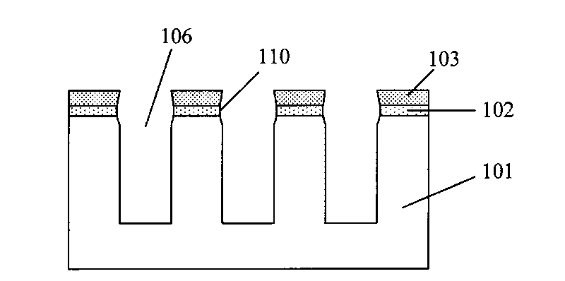
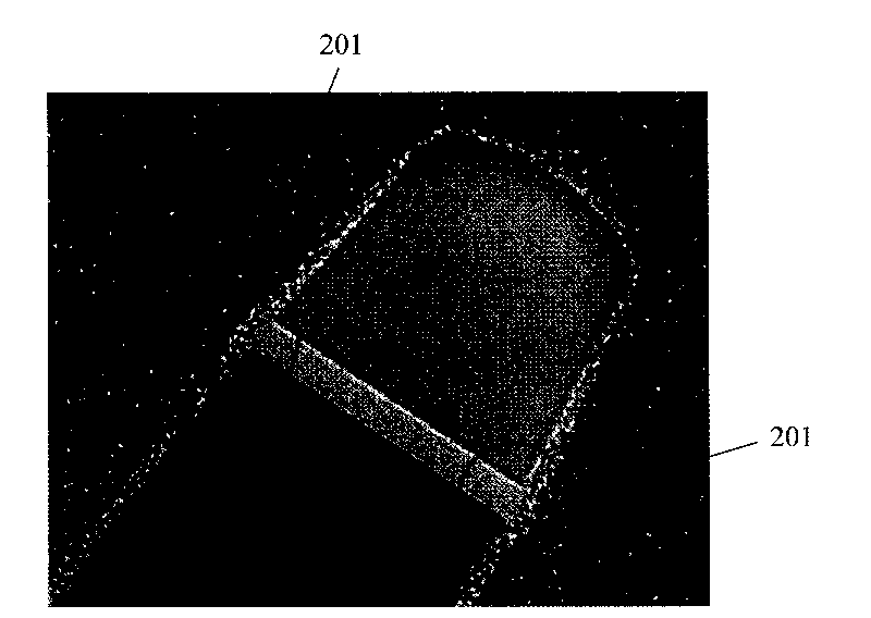
[0012] figure 2 For trench patterns formed using existing shallow trench isolation structure formation methods, such as figure 2 As shown in the middle circle 201, the sidewall of the formed trench is not smooth, and a depression appears on the top sidewall (the junction of the pad oxide layer and the silicon substrate), which will increase the leakage current of the device and be detrimental to the electrical performance of the device.
[0013] The Chinese patent application with publication number CN101162692A published on April 16, 2008 describes in detail a method for etching a silicon wafer, and specifically adjusts the etching process of the trench to form a circular groove at the top and bottom. Corner groove structure, but judging from its effect diagram, the shape of the groove formed by it is poor, and it is not suitable for small-sized devices with high requirements on shape and size.

Method used


Image

  • Method for making shallow groove insolation structure
  • Method for making shallow groove insolation structure
  • Method for making shallow groove insolation structure

Examples


Embodiment Construction

[0034] In order to make the above objects, features and advantages of the present invention more comprehensible, specific implementations of the present invention will be described in detail below in conjunction with the accompanying drawings.

[0035] The processing method of the present invention can be widely used in various fields, and can utilize many suitable materials to make, and the following is to illustrate by specific embodiment, certainly the present invention is not limited to this specific embodiment, in this field Common replacements known to those of ordinary skill undoubtedly fall within the protection scope of the present invention.

[0036] Secondly, the present invention is described in detail using schematic diagrams. When describing the embodiments of the present invention in detail, for the convenience of explanation, the cross-sectional view showing the device structure will not be partially enlarged according to the general scale, which should not be u...


PUM


Abstract

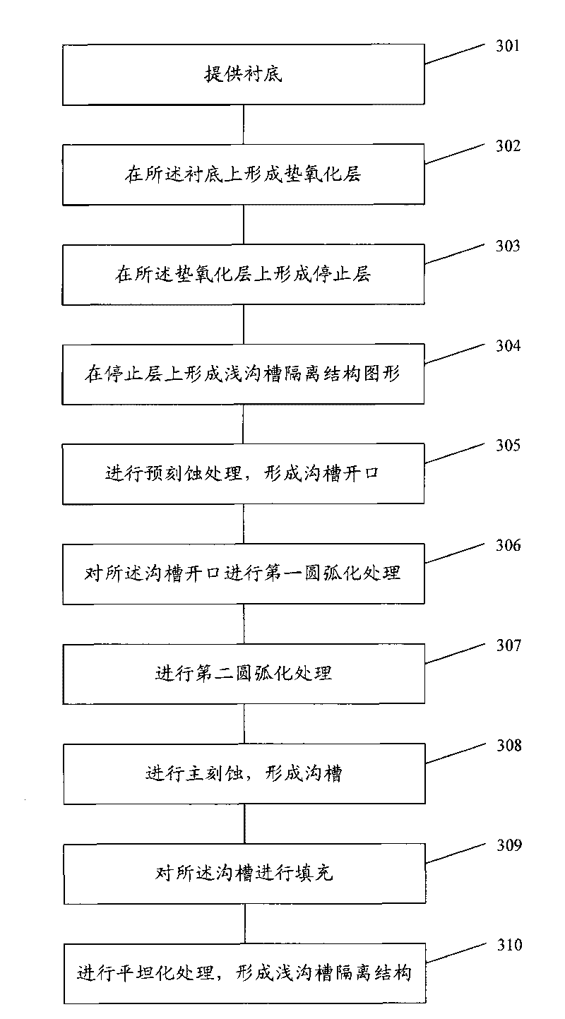
The present invention discloses a method for making a shallow groove insolation structure. The method comprises the steps: a padding oxide layer is formed on a substrate; a cease layer is formed on the padding oxide layer; a shallow groove insolation structure pattern is formed on the cease layer; the cease layer and the padding oxide layer are previously etched by taking the shallow groove insolation structure pattern as a covering film to form a groove opening; arc processing is carried out for the groove opening in at least two steps, and polymers produced from used gas in all steps are orderly reduced; the groove opening after arc processing is primarily etched to form a groove; the groove is filled; and a shallow groove insolation structure is formed after flattening processing. The adoption of the method for making a shallow groove insolation structure can ensure that the side walls on the top of the groove in the junction of a dielectric layer and the silicon substrate are smooth. The electrical properties of devices, such as current leakage, etc are effectively improved.

Description

technical field [0001] The invention relates to the technical field of semiconductor manufacturing, in particular to a method for forming a shallow trench isolation structure. Background technique [0002] The integrated circuit manufacturing process is a planar manufacturing process that combines photolithography, etching, deposition, ion implantation and other processes to form a large number of various types of complex devices on the same substrate and connect them to each other to have a complete electronic functions. Among them, any deviation in the process may cause the performance parameters of the circuit to deviate from the design value. At present, with the continuous proportional reduction of the device feature size of VLSI and the continuous improvement of integration level, higher requirements are put forward for the control of each step of the process and the accuracy of the process results. [0003] Take the shallow trench isolation structure formed in the s...

Claims


Application Information

Patent Timeline
Patent Type & Authority Applications(China)
IPC IPC(8): H01L21/762
Inventor 张海洋沈满华陈海华韩宝东
Owner SEMICON MFG INT (SHANGHAI) CORP
Why Eureka
Try Eureka