Broadband RFID UHF antenna and tag and manufacturing method of tag

An ultra-high frequency and antenna technology, applied in the field of transponders, can solve the problems that the range of action can only be one of far field or near field, the effect of antenna impedance matching is not ideal, and the use range of radio frequency transponders is limited. The steps are simple and convenient, the effect of optimizing the processing industry chain and reducing the position accuracy requirements

Active Publication Date: 2010-06-23
AEROSPACE INFORMATION
View PDF3 Cites 17 Cited by
  • Summary
  • Abstract
  • Description
  • Claims
  • Application Information

AI Technical Summary

Problems solved by technology

[0008] Regarding RFID antennas and antenna design methods, there are many patents in the prior art that have studied this, but the antennas in these prior art can only be applied to a single working mode, that is, their range of action can only be in the far field or one of the near fields
This greatly limits the range of use of radio frequency transponders
At the same time, the operating frequency range of the antennas in the prior art is limited to a narrow range even in the pure near-field range
[0009] And, since for a passive transponder, its energy comes entirely from the energy received by the antenna from the reader, even for an active transponder, the energy used for its information transmission also comes from the energy received by the antenna from the reader, therefore, The impedance matching of the antenna is very important for energy reception, and the impedance matching effect of the antenna in the prior art is not ideal in a wide operating frequency range

Method used


Image

  • Broadband RFID UHF antenna and tag and manufacturing method of tag
  • Broadband RFID UHF antenna and tag and manufacturing method of tag
  • Broadband RFID UHF antenna and tag and manufacturing method of tag

Examples


Embodiment Construction

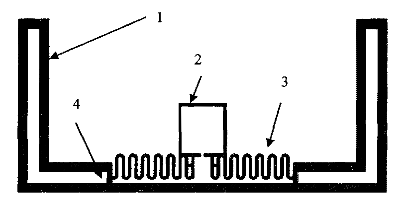
[0042] A specific embodiment of a broadband RFID ultra-high frequency antenna of the present invention is as follows figure 1As shown, it can be clearly seen from the figure that the antenna includes a near-field antenna and a far-field antenna combined in cascade. By combining far-field and near-field antennas, two different working modes, near-field and far-field, are realized. Wherein, preferably, the near-field antenna is an induction coil 2 , and the far-field antenna is a dipole antenna 1 . And, in order to realize impedance matching with the RFID chip, a serpentine line is connected in parallel between the induction coil of the RFID UHF antenna and the dipole antenna, one end of the serpentine line is connected with the induction coil 2, and the other end is connected with the dipole The stub 4 of the sub-antenna is connected.

[0043] Among them, the size of the dipole antenna is related to its operating frequency. For example, the length of the half-wavelength dipol...


PUM


Abstract

The invention discloses a broadband RFID UHF antenna, which is used for connecting a RFID chip; the characteristics are as follows: the antenna comprises a near-field antenna and a far-field antenna which are connected in cascade, and the near-field antenna and the far-field antenna are two separated parts which cling to each other to form the UHF antenna. Meanwhile, the invention also provides a RF tag using the antenna and a manufacturing method of the RF tag. The using of the RF antenna and the RF tag provided by the invention can obtain the following benefits: the working distance range of the antenna comprises the near-field range or the far-field range, and the working frequency range can cover the entire RFID UHF frequency band, therefore, the invention has wide range of adaptability. Meanwhile, in the range of the frequency band, the impedance value is stable, and good omni-directivity is provided at xz direction in the working frequency band.

Description

technical field [0001] The invention relates to a transponder in radio frequency identification (RFID) technology, in particular to an RFID ultra-high frequency antenna and an electronic tag in the transponder. Background technique [0002] The identification can be completed without physical contact between the transponder and the reader of the RFID system, so RFID has irreplaceable advantages over barcodes: First, it can identify a single very specific object instead of only identifying one object like a barcode. Second, using radio frequency, data can be read through external materials, while barcodes must rely on laser to read information; third, multiple objects can be read at the same time, while barcodes can only be read one by one. In addition, labels store a much larger amount of information than barcodes. [0003] The main distinguishing features of an RFID system include the operating frequency of the reader, the method of physical coupling between the reader and...

Claims


Application Information

Patent Timeline
Patent Type & Authority Applications(China)
IPC IPC(8): H01Q1/22H01Q21/00H01Q7/00H01Q9/16G06K19/077G06K19/07
Inventor 李其均张靖云汪柳平程辉王顺仁李万民翟春惠
Owner AEROSPACE INFORMATION
Why Eureka
Try Eureka