Ultrabroad band double-faced transition groove wire antenna using coplanar waveguide feed

A technology of gradient slot line and coplanar waveguide, which is used in antennas, antenna supports/installation devices, electrical components, etc., can solve the problems of insufficient bandwidth of radiation pattern and gain, and achieve good radiation characteristics and good radiation. Performance, the effect that is conducive to mass production

Inactive Publication Date: 2010-06-23
SOUTHEAST UNIV
View PDF5 Cites 9 Cited by
  • Summary
  • Abstract
  • Description
  • Claims
  • Application Information

AI Technical Summary

Problems solved by technology

It has been reported abroad that the antipodal tapered slot line fed by a strip line can broaden the impedan...

Method used


Image

  • Ultrabroad band double-faced transition groove wire antenna using coplanar waveguide feed
  • Ultrabroad band double-faced transition groove wire antenna using coplanar waveguide feed
  • Ultrabroad band double-faced transition groove wire antenna using coplanar waveguide feed

Examples


Embodiment Construction

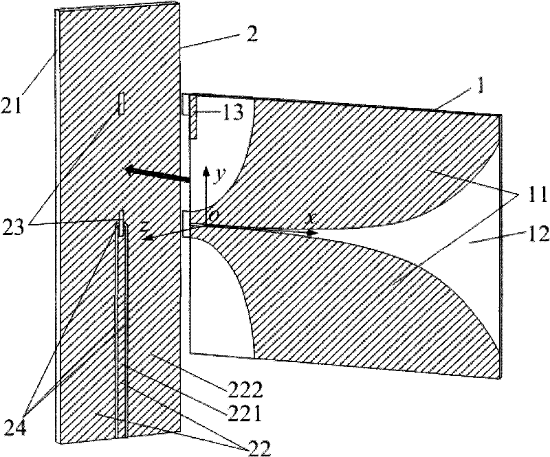
[0011] The invention is composed of double-sided printed gradient groove lines and a rear backplane. Its double-sided gradient groove line is composed of a dielectric board and metal layers printed on both sides of the dielectric board; its rear backplane is composed of a dielectric board and a metal layer located inside the dielectric board. There is a slit cut in the center of the rear backplane, and a ∏-shaped symmetrical groove line spanning the center of the slit and extending downward at a 90° corner is arranged on the metal layer; the groove line divides the metal layer on the backplane into two parts. In this part, the metal inside the Π-shaped slot line becomes the central conduction band of the coplanar waveguide, and the metal outside the Π-shaped slot line becomes the ground plate of the coplanar waveguide. After one end of the double-sided tapered slot line is vertically inserted into the gap of the rear backplane, the metal on the upper side is in electrical cont...


PUM


Abstract

The present invention relates to an ultrabroad band double-faced transition groove wire antenna using coplanar waveguide feed, which is an antenna having the advantages of simple structure, low cost, easy mass production, ultrabroad band working property and high gain. The ultrabroad band double-faced transition groove wire antenna comprises a double-faced transition groove wire plate (1) and a back plate (2) which are mutually connected vertically, wherein the double-faced transition groove wire plates (1) is vertically inserted from a side groove (23) of the back plate (2) with a single-side metal layer (22); a welding location sheet (13) and a back plate metal (222) are welded to be fixed; a transition groove wire (11) of the upper half part of the double-faced transition groove wire plate (1) is welded with the back plate metal (222) to be fixed, and the transition groove wire (11) of the lower half part of the double-faced transition groove wire plate (1) is welded with a central conduction band (221) of a coplanar waveguide. Thus electric contact is ensured. An anharmonicity feed structure can effectively widen the working frequency band of the ultrabroad band double-faced transition groove wire antenna on the basis that the radiance of the ultrabroad band double-faced transition groove wire antenna is ensured.

Description

technical field [0001] The invention relates to a structural scheme for improving the frequency band characteristics of a tapered slot line antenna, in particular to a tapered slot line antenna working in a microwave frequency band. Background technique [0002] At present, the tapered slot line antenna used in the microwave frequency band guides along the direction of the gradual widening of the slot and radiates electromagnetic waves forward, which has the characteristics of wide frequency band and medium gain. Its impedance matching frequency band is mainly limited by the resonant feed structure. To further broaden the frequency band, a non-resonant feed structure should be used instead. It has been reported abroad that the antipodal tapered slot line fed by a strip line can broaden the impedance frequency band of the antenna, but the radiation pattern and the frequency band of the gain are still not wide enough. Contents of the invention [0003] Technical problem: T...

Claims


Application Information

Patent Timeline
IPC IPC(8): H01Q1/38H01Q13/08H01Q1/14
Inventor 章文勋章朋
Owner SOUTHEAST UNIV
Why Eureka
Try Eureka