Eccentric rotor and axial space type coreless vibration motor having the rotor

An eccentric rotor and gap-type technology, which is applied in electric components, telephone communications, electrical components, etc., can solve the problems of durability, bearing length reduction, unevenness and other problems, and achieve the effect of increasing the effective magnetic flux density

Inactive Publication Date: 2010-06-23
思考株式会社
View PDF6 Cites 0 Cited by
  • Summary
  • Abstract
  • Description
  • Claims
  • Application Information

AI Technical Summary

Problems solved by technology

[0006] In order to prevent the axial movement of the above-mentioned bearing, although it is only necessary to form a concave-convex part on the outer periphery of the bearing to bite into the resin, it becomes difficult to form the concave-convex when the bearing is miniaturized with an outer diameter of about 1.5mm and a length of 1.1mm, and The length of the bearing is reduced and the projected area of ​​the bearing is also reduced, so there is a problem of durability

Method used


Image

  • Eccentric rotor and axial space type coreless vibration motor having the rotor
  • Eccentric rotor and axial space type coreless vibration motor having the rotor
  • Eccentric rotor and axial space type coreless vibration motor having the rotor

Examples


Embodiment 1

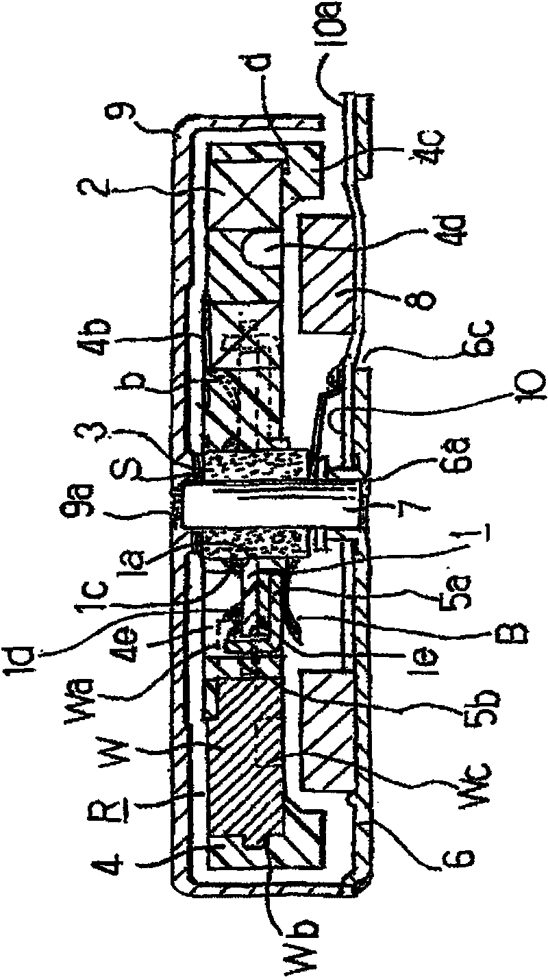
[0029] Figure 1 ~ Figure 3 In the axial gap type eccentric rotor R according to Embodiment 1 of the present invention, the following components are arranged: a printed wiring board 1 having a shaft support hole 1a formed in the center; A plurality of (here, three arranged at an arrangement pitch of 60°) hollow armature windings 2 that do not overlap the printed wiring board 1; bearings 3 that are assembled and joined to the above-mentioned shaft support hole 1a; A resin 4 with a temperature of 250° C. or higher is integrated with a partly welded eccentric weight W, and a plurality (here, 6 pieces) of commutator segments 5 are formed by covering the surface with noble metal.

[0030] The bearing 3 installed in the shaft support hole 1a of the above-mentioned printed wiring board 1 is soldered and bonded to the shaft support formed by printing with the solder part 1c after measuring its perpendicularity with a ruler, and then irradiated with laser light that does not easily tra...

Embodiment 2

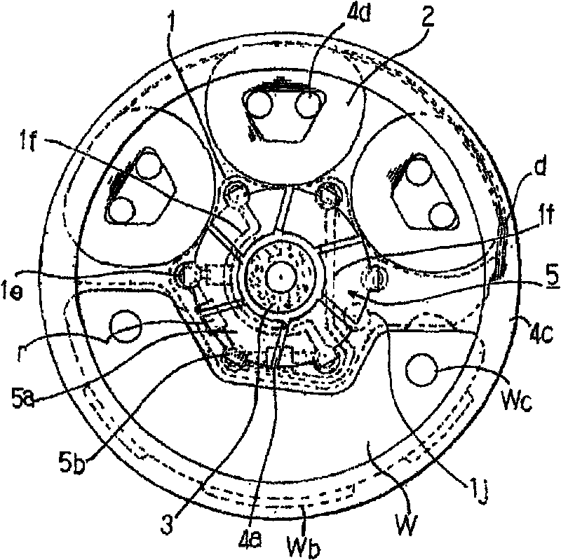
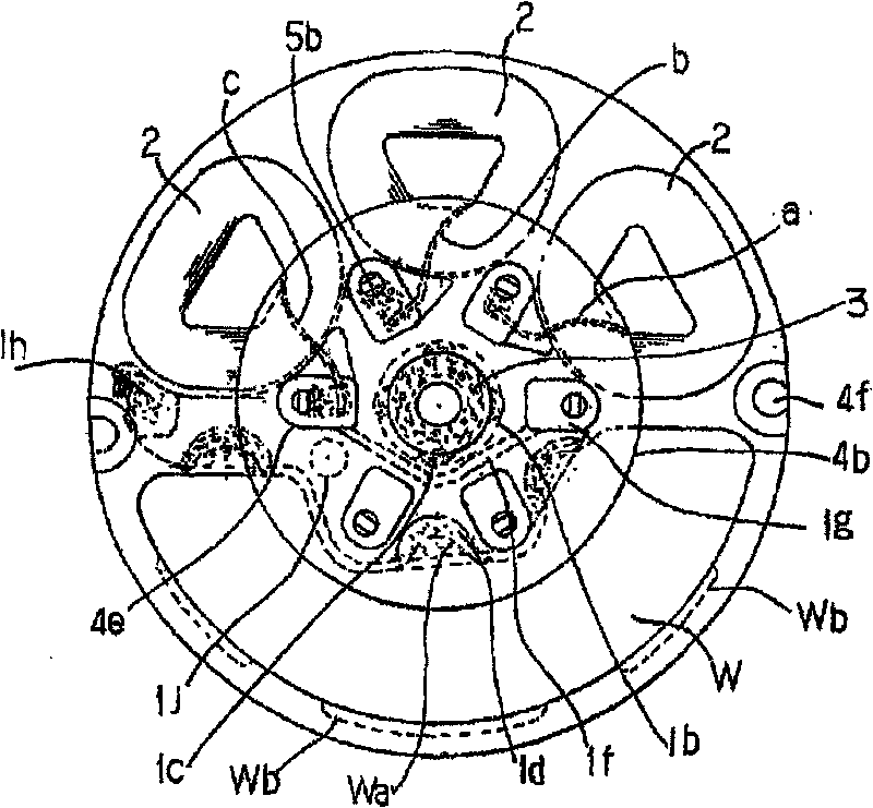
[0040] Figure 4 ~ Figure 6 middle, Figure 4 express image 3 Here is an embodiment in which two wire-wound hollow armature windings 22 are arranged at an opening angle of about 120 degrees, wherein the effective conductor part of the wire-wound hollow armature winding 22 is separated to the magnetic pole of the combined magnet. The degree of opening angle (here is 90°), thus improving the efficiency. Here, in order to ensure the efficiency of the coils, the printed wiring board 11 is overlapped with these coils to form a winding start connection pattern 11k, and a winding end unified connection pattern 11h is formed between each coil. The winding start end 22a of each coil 22, 22b is soldered to the above-mentioned winding start connection pattern 11k, and the winding end terminal 22d is soldered to the above-mentioned unified connection pattern 11h. The outer periphery of the sintered oil-impregnated bearing 3 is connected to the joining pattern 11b by soldering, which i...


PUM


Abstract

The present invention provides an eccentric rotor capable of ensuring build-in bearings to have enough holding strength and improving durability even though a motor is flat, and an axial space type coreless vibration motor having the rotor. The eccentric rotor is provided with a printed wiring board (1) with a shaft support hole (1a) on the center; a plurality of coreless armature windings (2); bearings (3) arranged on the position of the shaft support hole (1a) and conjoined to the printed wiring board (1) by circumference; an eccentric hammer (W), a main part of which is not overlapped with the printed wiring board (1); and a commutator (5) arranged on the printed wiring board (1).

Description

technical field [0001] The present invention relates to an improvement of an eccentric rotor suitable for use in a silent notification unit of a mobile communication device, and an axial gap type coreless vibration motor equipped with the rotor, and particularly relates to a shaft-fixed type adopting and ensuring sufficient bearing holding strength technology. Background technique [0002] Generally, the silent notification unit as a mobile communication device is a vibrating motor that utilizes centrifugal force to vibrate. This vibrating motor is usually equipped with an eccentric weight with a cross-section that is shaped like a ginkgo leaf on the output shaft of a rotary cylindrical motor. In addition, among the axial gap type flat motors, there are motors that generate centrifugal force vibration by using a built-in rotor itself. Since the rotor-built-in vibration motor does not require an output shaft, in recent years, the shaft-rotating type has been recommended to u...

Claims


Application Information

Patent Timeline
Patent Type & Authority Applications(China)
IPC IPC(8): H02K23/58H02K7/065
CPCH02K7/063H02K7/065H02K7/08H02K2203/03H04M19/047
Inventor 山口忠男
Owner 思考株式会社
Why Eureka
Try Eureka