
Magnetic field decoupling structure for direct-driven type magnetic suspension linear feed unit

A linear feed and drive type technology, applied in the direction of magnetic attraction or thrust holding device, electrical components, propulsion system, etc., can solve the problems of unmentioned decoupling, decoupling of magnetic field structure, etc., and achieve reasonable structure , the effect of easy installation

Inactive Publication Date: 2010-06-23
NANTONG UNIVERSITY
View PDF5 Cites 51 Cited by
  • Summary
  • Abstract
  • Description
  • Claims
  • Application Information

AI Technical Summary

Problems solved by technology

[0009] Nantong University (CN101136601A) proposed an intelligent magnetic levitation linear feed unit, in which a magnetic shield is installed outside the mover and stator of the linear motor to ensure that the magnetic flux leakage of the linear motor does not affect the normal operation of the system. Realized the magnetic field decoupling of the linear feed system and the magnetic levitation system, but did not mention the decoupling between the supporting electromagnet group, the guiding electromagnet group and the magnetic fields of the magnetic levitation system in terms of structure
[0010] "Magnetic Decoupling of Magnetic Suspension Feed Mechanism" published by Song Wenrong and others in "Optical Precision Engineering" and "Ultra-precision Magnetic Suspension Workbench and Its Decoupling Control" published in "Journal of Mechanical Engineering" by Li Lichuan et al. It solves the problem of magnetic field decoupling from the control method, and neither involves structural decoupling of the magnetic field

Method used


Image

  • Magnetic field decoupling structure for direct-driven type magnetic suspension linear feed unit
  • Magnetic field decoupling structure for direct-driven type magnetic suspension linear feed unit
  • Magnetic field decoupling structure for direct-driven type magnetic suspension linear feed unit

Examples


Embodiment Construction

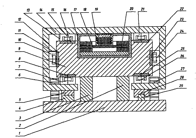
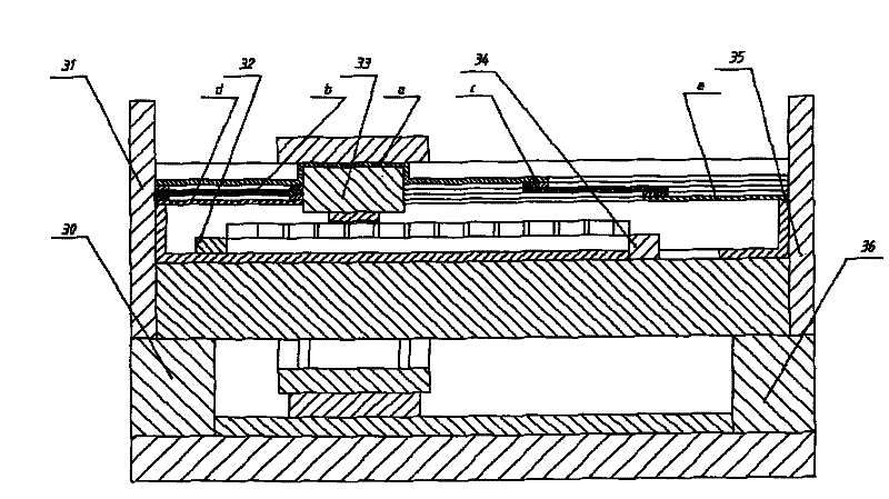
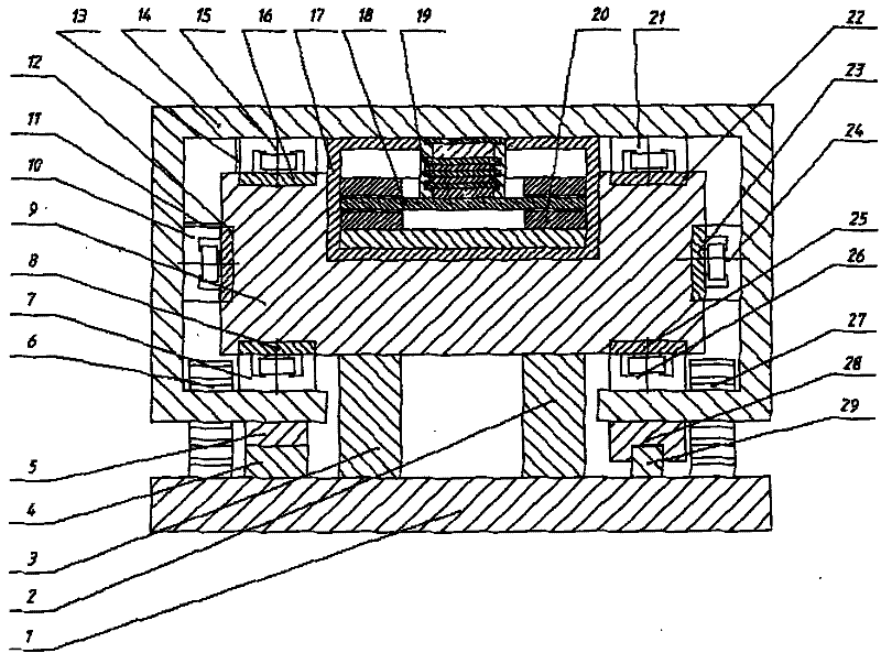
[0021] See attached figure 1 , 2 , a direct drive type magnetic levitation linear feed unit magnetic field decoupling structure, including a base 1, support blocks 2, 3, 30, 36 fixed on the base 1 and two auxiliary support static guide rails 4, 29; installed on the support block 2. The supporting guide rail 9 on 3; the workbench 14 on the outside of the support guide rail, the linear motor stator 20 installed in the center of the support guide rail 9, the mover 18 of the linear motor is installed on the inside of the workbench corresponding to the stator; on the workbench On the inner sides of the upper and lower sides, two pairs of bearing electromagnet groups (including supporting electromagnets 7, 15, 21, 26) arranged up and down are installed, and on the inner sides of the left and right sides of the workbench, there are oppositely arranged guiding electromagnet groups (including guiding electromagnet groups). Electromagnet 10,24), support guide rail comprises the main pa...


PUM


Abstract

The invention discloses a magnetic field decoupling structure for direct-driven type magnetic suspension linear feed unit. A supporting block is arranged on a base and the supporting block is provided with a supporting guide rail. The guide rail is sleeved with a workbench on the outside and an auxiliary support is arranged between the bottom of the workbench and the base; the stator of a linear motor is arranged on the center of the supporting guide rail and the rotor of the linear motor is arranged on the internal side of the workbench which corresponds to the stator. Two pairs of bearing electromagnet assemblies are arranged with each electromagnet facing to each other in the longitudinal direction on the insides of the upper and lower sides of the workbench and guiding electromagnet assemblies are arranged with each guiding electromagnet facing to each other on the insides of the left and right sides of the workbench. The supporting guide rail comprises a main body consisting of pure aluminum materials and pure ferrous suction plates are arranged on the part of the main body which is relative to the bearing electromagnet assemblies and guiding electromagnets and magnetic shielding covers are sleeved with the circumferential parts of the stator and rotor of the linear motor. The magnetic field decoupling structure for direct-driven type magnetic suspension linear feed unit has reasonable structure and thus can effectively achieve the magnetic field decoupling of the magnetic suspension linear feed unit from the aspect of structure.

Description

Technical field: [0001] The invention relates to a magnetic field decoupling structure of a direct-drive magnetic levitation linear feed unit. Background technique: [0002] Modern manufacturing technology is developing in the direction of high speed, precision and modularization. The manufacturing industry has put forward higher and higher requirements for the performance of processing equipment. This demand has promoted the development of machine tool industry, especially CNC machine tools. However, the industrialization scale and product level of functional components supporting CNC machine tools are far from meeting the development requirements of CNC machine tools. The feed unit is an important functional part of the CNC machine tool. The final coordinates and contour accuracy of the processed workpiece are affected by the transmission accuracy, sensitivity and stability of the feed unit movement. Therefore, it must have small frictional resistance, high transmission ac...

Claims


Application Information

Patent Timeline
IPC IPC(8): H02N15/00H02K41/02
Inventor 廖萍吴国庆马苏扬倪红军茅靖峰朱昱姜安栋
Owner NANTONG UNIVERSITY
Learn More