Electromagnetic oven power automatic calibration method and circuit

A technology of automatic calibration and induction cooker, applied in the field of induction cooker, can solve the problems of large error, offset of potentiometer resistance value, and large power error of induction cooker, and achieves the effect of simple application circuit, cost saving, and increased difficulty.

Active Publication Date: 2010-06-23
SHENZHEN CHK
View PDF4 Cites 9 Cited by
  • Summary
  • Abstract
  • Description
  • Claims
  • Application Information

AI Technical Summary

Problems solved by technology

Because the error of this method is relatively large, according to the linear expression y=kx+b (k≠0), it is generally necessary to use a potentiometer to adjust to correct the coefficient k in the formula. During use, the potentiometer is prone to resistance value deviation, resulting in a large error in the power of the induction cooker

Method used


Image

  • Electromagnetic oven power automatic calibration method and circuit
  • Electromagnetic oven power automatic calibration method and circuit
  • Electromagnetic oven power automatic calibration method and circuit

Examples


Embodiment Construction

[0021] The present invention will be further described below in conjunction with the accompanying drawings.

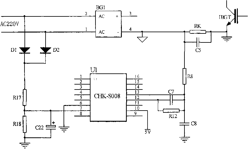
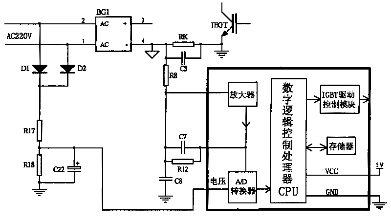
[0022] refer to figure 1 , 2 , the power automatic calibration circuit of the induction cooker mainly includes: a current detection acquisition circuit, a voltage detection acquisition circuit, a memory and a digital logic control processor CPU.

[0023] The current detection and acquisition circuit includes a current sampling circuit, an amplifier and an A / D converter, and the amplifier is connected between the current sampling circuit and an input terminal of the A / D converter. Wherein, the current sampling circuit includes a constantan wire resistor RK connected in series between the rectifier bridge BG1 and the IGBT drain, and a resistor R8 connected to the constantan wire resistor RK. One end of the resistor R8 is connected to the input end of the amplifier (i.e. figure 2 13Pin of the CHK-S008 chip in the center), the amplifier input and output (ie figure 2 1...


PUM


Abstract

The invention relates to an electromagnetic oven power automatic calibration method which comprises the following steps of: 1. selecting two current test values within the working current range of an electromagnetic oven, enabling the electromagnetic oven to operate under the conditions of the current test values and zero and detecting the voltage values of current signals under the three operating conditions; computing a coefficient k and an intercept b by a CPU (Central Processing Unit) by adopting three groups of data according to a formula y(i)=k*i+b and storing; and 2. when in working, computing a current current signal i by the CPU by adopting the voltage value y(i) of the current current signal detected by a current detection and acquisition circuit and the k and b according to a formula i=1 / k*y(i)-b / k and then computing the current power according to the current current signal and a current voltage signal. A calibration procedure is built in a chip to set the automatic acquisition of parameters and compute and calibrate the parameters; and when in working, the electromagnetic oven power automatic calibration method can automatically calibrate the current or the power, provides an accurate basis for the adjustment of the electromagnetic oven power, can replace the calibration mode of a traditional potentiometer, saves the cost and has improved reliability.

Description

technical field [0001] The invention relates to electromagnetic cooker technology, in particular to an automatic power calibration method and a calibration circuit for an electromagnetic cooker. Background technique [0002] Ordinary induction cooker calculates the power of induction cooker by detecting the current working voltage and current, and calculates the current power through the formula of power = voltage × current. [0003] The current sampling circuit generally uses a transformer or a constantan wire resistance to sample a small current signal and convert it into a voltage signal, which is then amplified for calculation. Because the error of this method is relatively large, according to the linear expression y=kx+b (k≠0), it is generally necessary to use a potentiometer to adjust to correct the coefficient k in the formula. During use, the potentiometer is prone to resistance value deviation, resulting in a large error in the power of the induction cooker. [00...

Claims


Application Information

Patent Timeline
Patent Type & Authority Applications(China)
IPC IPC(8): H05B6/06
CPCH05B6/06H05B6/68
Inventor 丘守庆许申生刘春光李鹏陈劲锋
Owner SHENZHEN CHK
Why Eureka
Try Eureka