Municipal power constant current LED lamp circuit

An LED lamp circuit, electric constant current technology, applied in the direction of electric lamp circuit layout, circuit layout, electric light source, etc., can solve the problems of high comprehensive manufacturing cost, many components, workload, etc., to expand the market scale and reduce the sales price. , the effect of reducing production costs

Inactive Publication Date: 2010-06-23
深圳市明连兴光电科技有限公司
View PDF5 Cites 8 Cited by
  • Summary
  • Abstract
  • Description
  • Claims
  • Application Information

AI Technical Summary

Problems solved by technology

[0008] In addition, if you conduct a slightly comprehensive analysis of the power adapter, you will know that the constant current source based on PWM technology has several inherent deficiencies.
First of all, its energy conversion efficiency is generally only about 80-90%, and it is difficult to achieve more than 95%; secondly, the circuit structure is relatively complex, there are many components, the control of distributed parameters requires experience, the overall manufacturing cost is high, and the volume is small. It is relatively large; again, measurement and debugging must rely on instruments and meters, and professional technology has high requirements, and debugging and troubleshooting work has certain difficulty and workload, which increases part of the cost; finally, the circuit reliability model is more complicated, constant The reliability index of the flow source subsystem is relatively low, that is to say, its MTBF index is not high enough, which may eventually affect the overall reliability index of LED lighting fixtures.

Method used


Image

  • Municipal power constant current LED lamp circuit
  • Municipal power constant current LED lamp circuit
  • Municipal power constant current LED lamp circuit

Examples


Embodiment 1

[0023] Embodiment 1. AC220V / 50Hz mains grid connected to E26 rotary 5W single-head LED lamp

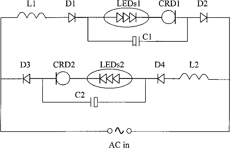
[0024] In this embodiment, the 5W single-head LED lighting circuit is as follows: figure 2 shown.

[0025] The light source part of each channel is composed of 90 LEDs in series, with CRD devices in series, and its constant current working current Iw=15mA; the isolation diodes D1, D2, D3, and D4 are composed of four 1N4007 discrete diodes; the capacitor is made of high-quality 10uF / 400V electrolytic Capacitors, inductors at least 47mH, the circuit works fine with little to no debugging. The 5W single-head LED lighting circuit uses a total of 180 LEDs.

Embodiment 2

[0026] Embodiment 2, AC220V / 50Hz mains grid connected to 10W-LED module lamp

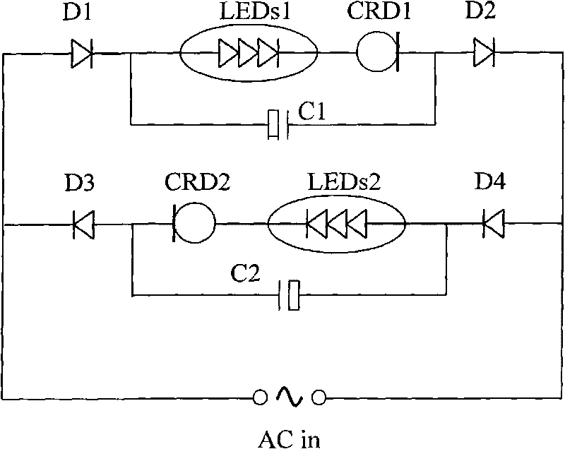
[0027] The circuit schematic diagram of this embodiment is two figure 2 The parallel connection, production and processing are almost the same, but the appearance of the lamp is changed from the original E26 bulb type to a brick-like LED light source module. The production is simple and the work is normal.


PUM


Abstract

The invention discloses an LED lighting lamp circuit directly used for the power supply of a municipal electric network. A low-cost resistive-capacitive and voltage-reducing driving circuit has simple structure and low cost, but has poor performance and low efficiency, and can damage an LED light source device to a certain degree; a series voltage regulating circuit has large volume, heavy weight, more heating, low efficiency, high cost and no energy saving; a PWM voltage regulating or constant current switch has relatively good power supply performance and higher efficiency, but has relatively higher cost, low MTBF index and low reliability, and can also introduce EMI electromagnetic interference. The invention has the advantages of good constant current effect, low cost, high efficiency, long life and no EMI. The key to realize the advantages is that two ways of series LED light source circuits reversely connected in parallel are adopted, and each way is connected with a CRD device to realize constant current; and L and C are adopted to realize PFC and suppress voltage fluctuation, and the power factor and lighting effect are improved under the premise of keeping the structure of the circuit simple and the cost low.

Description

【Technical field】 [0001] The invention relates to an LED illuminating lamp circuit, in particular to an LED illuminating lamp circuit which can be used for direct power supply by a municipal power grid, has high power consumption efficiency and good lighting effect, and has a simple structure, low cost, low cost and long service life. [0002] LED lighting is an emerging industry that has risen rapidly over the years, and LED lighting sources have in fact become the third generation of artificial electric light sources. Due to the high efficiency, longevity, lightness and firmness of LED light sources, as well as the green and environmental protection of materials and manufacturing processes, LED lighting sources are significantly better than any previous artificial electric light sources. However, due to the high comprehensive cost of LED light sources at the current stage, the sales price of application products remains high. In the face of all kinds of attractive LED light...

Claims


Application Information

Patent Timeline
Patent Type & Authority Applications(China)
IPC IPC(8): H05B37/00F21V23/00F21Y101/02
Inventor 李旭明
Owner 深圳市明连兴光电科技有限公司
Why Eureka
Try Eureka