Energy-saving durable dewatering and drying centrifuge

A centrifuge and durable technology, applied in the field of centrifuges, can solve the problems of long spindle, heavy weight and large yaw, and achieve the effects of improving production efficiency, improving service life and reducing yaw.

Inactive Publication Date: 2010-06-30
成都崇安科技有限公司
View PDF0 Cites 3 Cited by
  • Summary
  • Abstract
  • Description
  • Claims
  • Application Information

AI Technical Summary

Problems solved by technology

[0002] At present, the centrifuges used for dehydration and drying after electroplating and cleaning of electronic components and parts are one kind of domestic general centrifuge, which uses marble discs as bearings to rotate. There are many parts used for dehydration and drying, which are heavy and have a large centrifugal force. Bad, the dehydration and drying barrel has no heating device, after the parts are dehydrated and dried, there are water spots, and the product quality cannot be guaranteed
The other is the dehydration and drying centrifuge imported from Japan and Germany. Its structure is basically the same. One is that a heating device is installed under the dehydration and drying barrel. The high-carbon apron is used as the bearing, but because the heating device is installed under the dehydration and drying barrel and the brake device is on the main shaft, the main shaft is longer, and the deflection is relatively large during rotation. It is often worn out, and usually needs to be repaired and replaced after about three months of use. The high-carbon apron is an imported part, which is expensive, which not only increases the cost, but also is difficult to disassemble and troublesome, which affects production. Because the heating device is under the dehydration barrel , preheat 2 hours in advance when using

Method used


Image

  • Energy-saving durable dewatering and drying centrifuge
  • Energy-saving durable dewatering and drying centrifuge
  • Energy-saving durable dewatering and drying centrifuge

Examples


Embodiment Construction

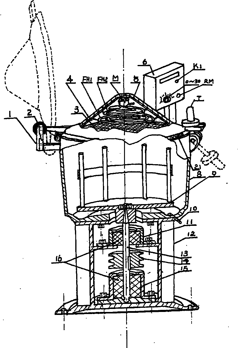
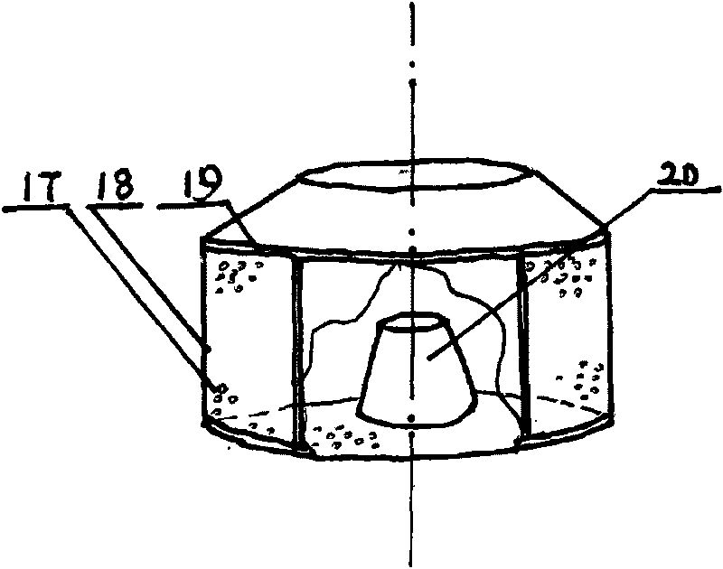
[0011] Referring to the figure, in the energy-saving and durable dewatering and drying centrifuge of the present invention, the main shaft (13) in the middle of the lower support (12) of the centrifuge is made of high-carbon rubber rings (16) fixed in the upper and lower stable seats (11, 15). Bearing sleeve, the upper end of the main shaft passes through the upper seat dewatering and drying bucket (8) and is connected and fixed with the stainless steel plate (9) containing the stainless steel parts dewatering basket (18). , The centrifuge cover (4) on the dehydration and drying bucket is equipped with a far-infrared tapered reflector rapid heat heating device. The power supply switch of the heating device is completed by the contacts in the reed switch (1) that are not corroded. The permanent magnet (2) installed in the rotating part behind the opening and closing of the centrifuge cover controls the connection and disconnection of the contacts in the reed switch. When the cen...


PUM


Abstract

The invention discloses an energy-saving durable dewatering and drying centrifuge, which is used for dewatering and drying electronic components in an electroplating production line after washing. A main shaft (13) in the middle of a lower support (12) of the centrifuge uses a high-carbon rubber ring (16) in an upper stabilized seat (11) and a lower stabilized seat (15) as a bearing bush; the main shaft passes through an upper seat dewatering dryer (8) to be connected and fixed with a stainless steel disk (9) of a basket (18) for accommodating stainless steel parts; a far-infrared taper reflector (5) quick heater is arranged below a centrifuge cover (4); the heater is supplied with power by the connecting and disconnecting of the contacts in a reed pipe (1); the reed pipe is controlled by a permanent magnet (2) arranged at the rotary position of the centrifuge cover; the fact that the centrifuge cover is closed means that electrification heating is performed, and the fact that the centrifuge cover is open means outrage and heating termination; a timer (22) is arranged according to the quantity and complexity degree of parts; and the centrifuge is shut down automatically after dewatering and drying of parts.

Description

technical field [0001] The invention relates to an electroplating production line, which is used for a centrifuge for dehydration and drying of electroplating electronic component parts after cleaning. Background technique [0002] At present, the centrifuge used for dehydration and drying after electroplating and cleaning of electronic component parts is a domestic general centrifuge, which uses a marble disc as a bearing for rotation. If it is damaged, the dehydration and drying bucket has no heating device. After the parts are dehydrated and dried, there are water stains, which cannot guarantee the quality of the product. The other is the introduction of dehydration and drying centrifuges from Japan and Germany. The structure is basically the same. First, a heating device is installed under the dehydration and drying barrel. The high-carbon rubber ring is used as the bearing, but because the heating device is installed under the dehydration and drying bucket and the brak...

Claims


Application Information

Patent Timeline
Patent Type & Authority Applications(China)
IPC IPC(8): F26B7/00
Inventor 石毓忠陈金华
Owner 成都崇安科技有限公司
Why Eureka
Try Eureka